Abrasive band machine

An abrasive belt machine and abrasive belt technology are applied in the field of abrasive belt machines, which can solve the problems of wire breakage and increase the risk of short circuit, and achieve the effects of simple operation, comfortable operation and convenient adjustment.

Inactive Publication Date: 2010-02-17
POSITEC POWER TOOLS (SUZHOU) CO LTD
View PDF6 Cites 0 Cited by
  • Summary
  • Abstract
  • Description
  • Claims
  • Application Information

AI Technical Summary

Problems solved by technology

Second, for the wires connected to the power switch, they are set on the movable handle and can rotate relative to the motor along the handle. Every time the handle is adjusted to a new position, the wires will bear torsion and bending. Even if soft flexible wires are used, the time Long wires also run the risk of breaking, thereby increasing the risk of a short circuit

Method used


Image

  • Abrasive band machine
  • Abrasive band machine
  • Abrasive band machine

Examples


Embodiment Construction

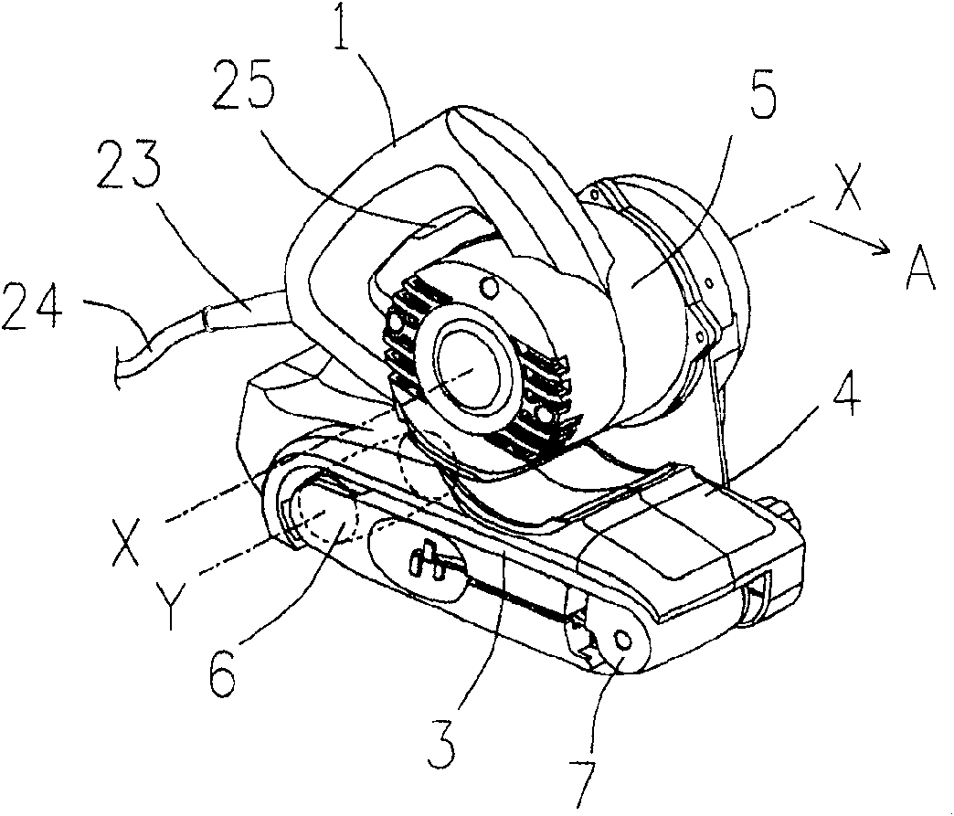
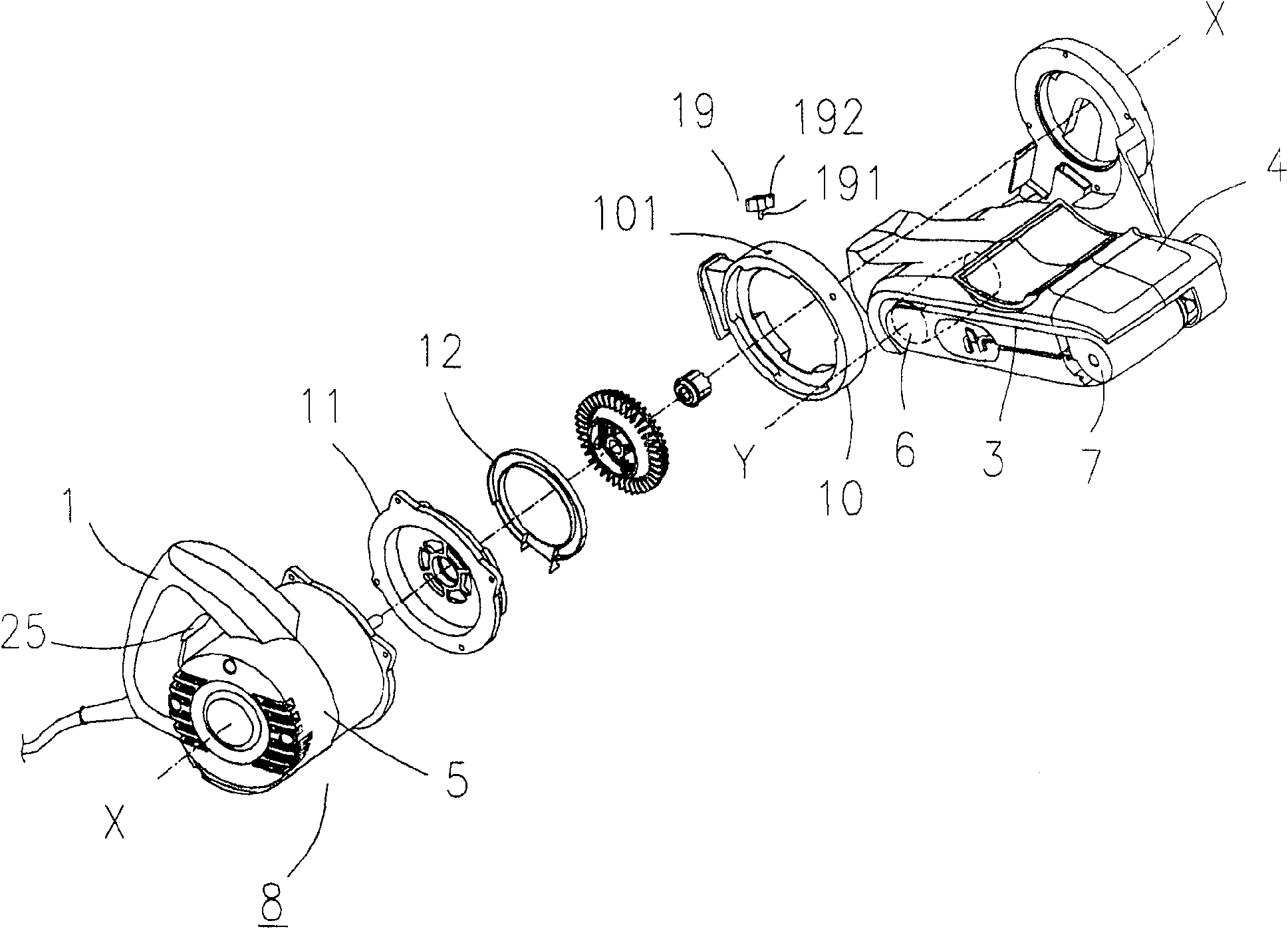
[0019] See attached Figure 1~6 , the present invention discloses a belt machine, comprising a handle 1, a motor 2, an abrasive belt 3 for sanding workpieces, an abrasive belt housing 4, a motor housing 5, a driving wheel 6, and a driven wheel 7.

[0020] The abrasive belt 3 is annular, and connects the driving wheel 6 and the driven wheel 7 . The driving wheel 6 has a longitudinal axis Y. The motor 2 is accommodated in the motor housing 5, the motor 2 has a motor shaft 21, the motor shaft 21 defines a longitudinal axis X, the longitudinal axis X of the motor 2 is parallel to the driving wheel The longitudinal axis Y. One end of the motor shaft 21 is connected with a gear 22 , and the gear 22 drives the driving wheel 6 to rotate through a transmission device 16 , thereby driving the driven wheel 7 to rotate through the abrasive belt 3 . The abrasive belt 3 , the driving wheel 6 , the driven wheel 7 and the transmission device 16 are all arranged in the abrasive belt housing...


PUM


Abstract

An abrasive band machine is composed of abrasive band and its casing, motor and its casing, handle connected to motor casing to become a unit, drive gear, driven gear, driver unit linking motor to drive gear and connector for connecting said unit to abrasive band casing in order to relax the fatigue of operator.

Description

technical field [0001] The invention relates to a belt sander, especially a belt sander with a rotary handle. Background technique [0002] Traditional belt sanders generally have a shell, on which a handle is generally arranged, which is convenient for the operator to hold. A motor is arranged in the shell, and the motor drives the driving wheel of the belt sander to rotate through the transmission device. The rotation of the driving wheel The driven wheel is driven by the abrasive belt to rotate to complete the sanding work. U.S. Patent No. 6,475,075 discloses the above-mentioned belt sander, wherein the rotation axis of the motor is parallel to the rotation axis of the driving wheel, and the position of the handle is fixed, so when operating on a vertical, inclined or very long workpiece There is a disadvantage that the operator has to turn the wrist, and in this state, working for a long time will cause fatigue. [0003] U.S. Patent No. 6,588,112 discloses a power tool...

Claims


Application Information

Patent Timeline
Patent Type & Authority Patents(China)
IPC IPC(8): B24B23/06
Inventor 强尼·鲍瑞那图
Owner POSITEC POWER TOOLS (SUZHOU) CO LTD
Why Eureka
Try Eureka