Multi-head double-fuel combined nozzle
A dual-fuel, multi-head technology, used in burners, injection devices, liquid injection devices, etc., can solve the problems of poor nozzle atomization, inconvenient installation and maintenance, and low combustion efficiency, and improve the quality of the outlet temperature field. , Easy installation and maintenance, and the effect of improving combustion efficiency
- Summary
- Abstract
- Description
- Claims
- Application Information
AI Technical Summary
Problems solved by technology
Method used
Image
Examples
Embodiment 1
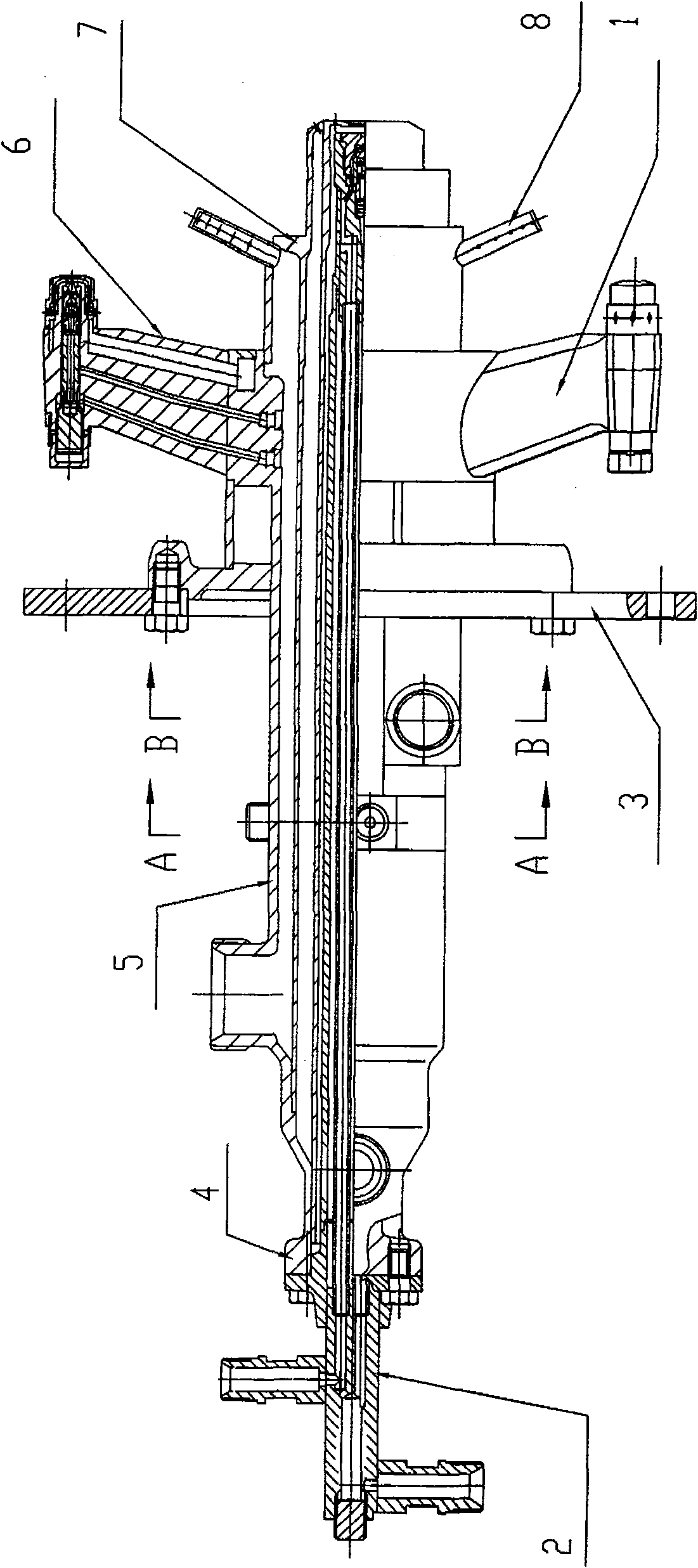
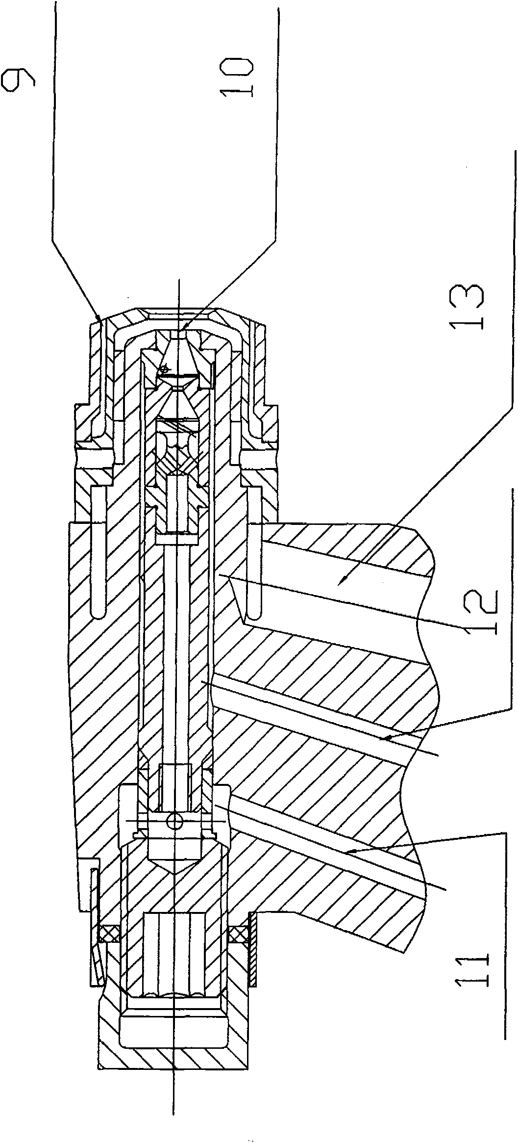
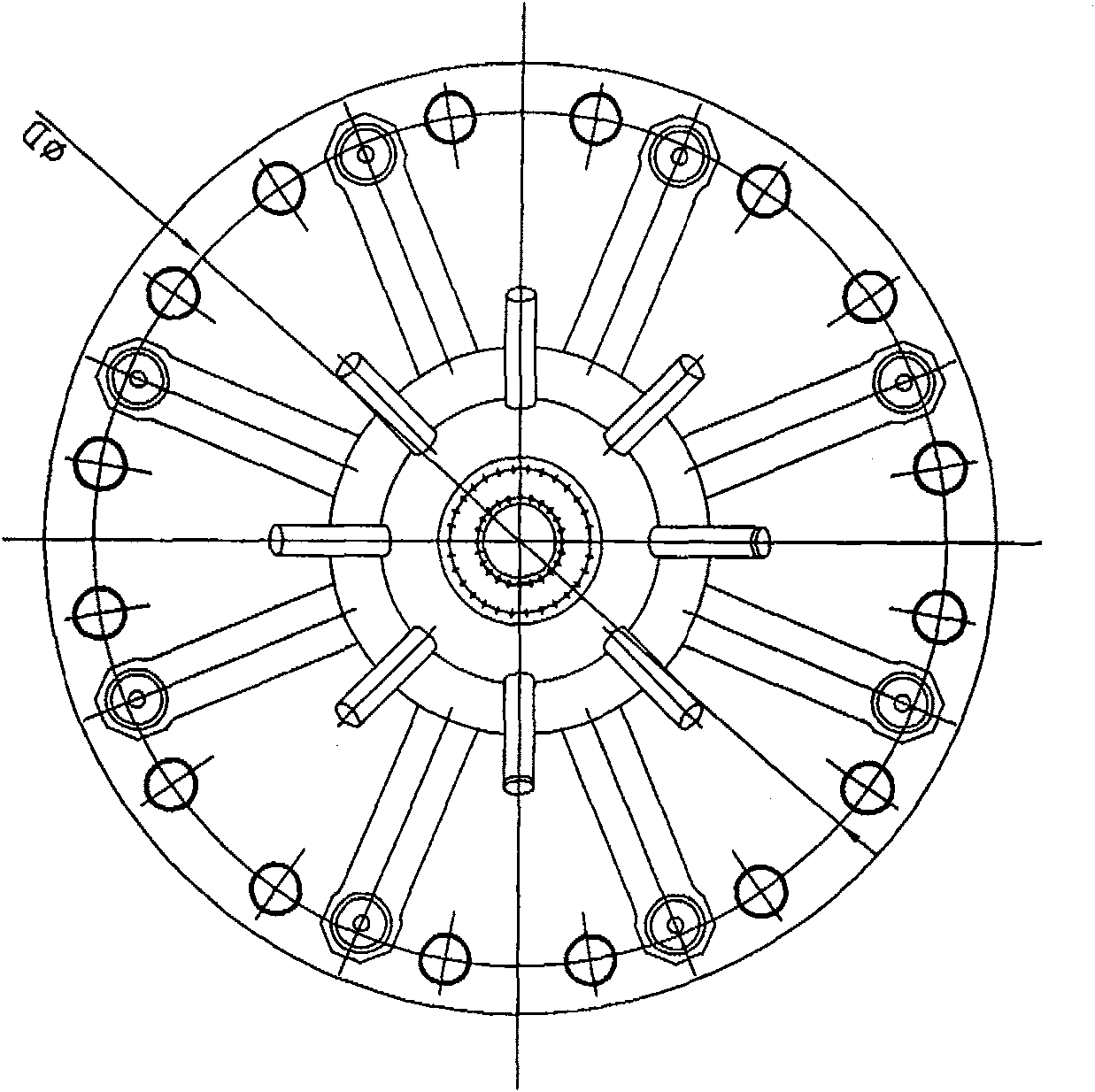
[0023] A multi-head dual-fuel combined nozzle. The multi-head dual-fuel combined nozzle in this embodiment includes a head nozzle 1, a central nozzle group 2, a nozzle mounting edge 3, a central liquid fuel nozzle mounting edge 4, and a nozzle housing 5; the nozzle housing 5 includes a head nozzle housing 6 and a central nozzle housing 7; the central nozzle group 2 includes a gas fuel nozzle 8, a duty nozzle 9, and a central liquid fuel nozzle 10; wherein the central liquid fuel nozzle 10 is a double Oil circuit centrifugal atomizing nozzle, the central liquid fuel nozzle 10 is connected with the central nozzle housing 7 through the central liquid fuel nozzle mounting edge 4; the central nozzle housing 7 passes through the center of the central nozzle group 2, and is formed by the right The side end surface protrudes; the head nozzle 1 is an independent dual-fuel nozzle, including three fuel passages of the first fuel passage 11, the second fuel passage 12, and the third fuel p...
Embodiment 2
[0028] A multi-head dual-fuel combined nozzle. The multi-head dual-fuel combined nozzle in this embodiment includes a head nozzle 1, a central nozzle group 2, a nozzle mounting edge 3, a central liquid fuel nozzle mounting edge 4, and a nozzle housing 5; the nozzle housing 5 includes a head nozzle housing 6 and a central nozzle housing 7; the central nozzle group 2 includes a gas fuel nozzle 8, a duty nozzle 9, and a central liquid fuel nozzle 10; wherein the central liquid fuel nozzle 10 is a double Oil circuit centrifugal atomizing nozzle, the central liquid fuel nozzle 10 is connected with the central nozzle housing 7 through the central liquid fuel nozzle mounting edge 4; the central nozzle housing 7 passes through the center of the central nozzle group 2, and is formed by the right The side end surface protrudes; the head nozzle 1 is an independent dual-fuel nozzle, including three fuel passages of the first fuel passage 11, the second fuel passage 12, and the third fuel p...
Embodiment 3
[0033] A multi-head dual-fuel combined nozzle. The multi-head dual-fuel combined nozzle in this embodiment includes a head nozzle 1, a central nozzle group 2, a nozzle mounting edge 3, a central liquid fuel nozzle mounting edge 4, and a nozzle housing 5; the nozzle housing 5 includes a head nozzle housing 6 and a central nozzle housing 7; the central nozzle group 2 includes a gas fuel nozzle 8, a duty nozzle 9, and a central liquid fuel nozzle 10; wherein the central liquid fuel nozzle 10 is a double Oil circuit centrifugal atomizing nozzle, the central liquid fuel nozzle 10 is connected with the central nozzle housing 7 through the central liquid fuel nozzle mounting edge 4; the central nozzle housing 7 passes through the center of the central nozzle group 2, and is formed by the right The side end surface protrudes; the head nozzle 1 is an independent dual-fuel nozzle, including three fuel passages: the first fuel passage 11, the second fuel passage 12, and the third fuel pas...
PUM
 Abstract
Description
Claims
Application Information
 - R&D
- Intellectual Property
- Life Sciences
- Materials
- Tech Scout
- Unparalleled Data Quality
- Higher Quality Content
- 60% Fewer Hallucinations
Browse by: Latest US Patents, China's latest patents, Technical Efficacy Thesaurus, Application Domain, Technology Topic, Popular Technical Reports.
© 2025 PatSnap. All rights reserved.Legal|Privacy policy|Modern Slavery Act Transparency Statement|Sitemap|About US| Contact US: help@patsnap.com


