Heart monitor with remote alarm capability

A monitoring device, monitoring system technology, applied in the field of medical monitoring and notification, to achieve the effect of increasing mobility, reducing size and cost

Inactive Publication Date: 2010-02-24
KONINKLIJKE PHILIPS ELECTRONICS NV
View PDF7 Cites 0 Cited by
  • Summary
  • Abstract
  • Description
  • Claims
  • Application Information

AI Technical Summary

Problems solved by technology

[0007] Another problem is that a patient may want someone close to him or her to handle or oversee the emerg

Method used


Image

  • Heart monitor with remote alarm capability
  • Heart monitor with remote alarm capability

Examples


Embodiment Construction

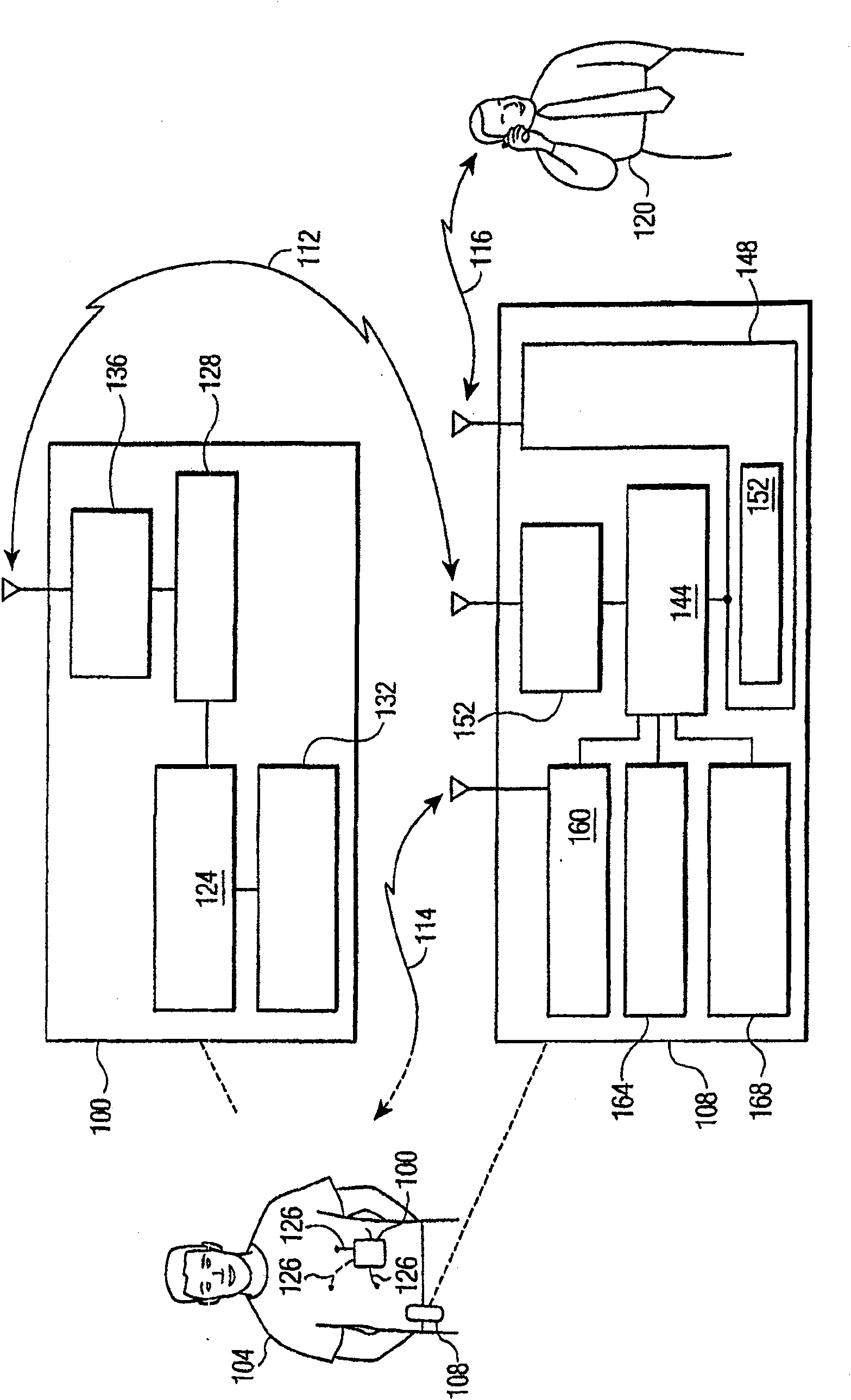
[0017] figure 1 is a conceptual block diagram and flowchart of an exemplary portable medical monitoring device 100 in accordance with a preferred embodiment of the present invention. Detailed descriptions of well-known elements and features have been omitted for clarity of presentation.

[0018] exist figure 1 In this example, a patient 104 wears the device 100, and the mobile phone 108 is attached to the patient's clothing. Respective dotted lines extending from device 100 and phone 108 point to more detailed views of the devices in the block diagram. A wireless signal 112 from the device 100 to the phone 108 reports an emergency, a wireless signal 114 from a satellite (not shown) provides the phone's current location, and a responsive wireless signal 116 from the phone initiates a call to the trusted recipient. 120, the recipient 120 will offer or call for help.

[0019] Monitoring device 100 includes monitoring device 124, which may be a microprocessor and in the implem...


PUM


Abstract

A mobile phone (108) is configured as an adjunct to a medical monitoring device (100) to make an emergency phone call (228) to a predetermined, trusted care-giver or -overseer (120) when an abnormal medical condition is detected by the device(204). The phone and the device preferably communicate wirelessly with each other, as through a Bluetooth connection (212). Preferably, the phone is equippedto play back a pre-recorded voice message on the phone call (236), which may include the current location of the patient (216, 220), instructions personalized to the care-giver (168), and an image orvideo playback of the patient. The phone may concurrently page emergency medical services.

Description

technical field [0001] The present invention relates to medical monitoring and notification in the event of an emergency. The present invention is particularly focused on mobile devices for monitoring and notification. Background technique [0002] Heart disease is the leading killer. Often, a fatal heart attack is preceded by no noticeable or already noticed symptoms. In other cases, a person may know that he or she has a heart condition and may wish to be prepared to be able to detect an abnormal heart condition and call for help immediately. [0003] US Patent 6,579,231 to Phipps, entitled "Personal Medical Monitoring Unit and System," describes a mobile medical monitoring unit designed to be worn by a patient, the contents of which are incorporated herein by reference in their entirety. When the unit detects a patient with an adverse medical condition, it sends a wireless signal to a communications network that relays the alert to a 911 call center and a central repor...

Claims


Application Information

Patent Timeline
IPC IPC(8): A61B5/00A61B5/332
CPCA61B5/0002A61B5/1112
Inventor G·布罗克-费希尔
Owner KONINKLIJKE PHILIPS ELECTRONICS NV
Why Eureka
Try Eureka