Catheter, apparatus and method for therapeutic embolization

A therapeutic, catheter-based technology that can be used in applications, surgical navigation systems, medical science, etc., and can solve problems such as not giving

Inactive Publication Date: 2010-02-24
KONINK PHILIPS ELECTRONICS NV
View PDF5 Cites 2 Cited by
  • Summary
  • Abstract
  • Description
  • Claims
  • Application Information

AI Technical Summary

Problems solved by technology

However, no further details were given on how to achieve this

Method used


Image

  • Catheter, apparatus and method for therapeutic embolization
  • Catheter, apparatus and method for therapeutic embolization

Examples


Embodiment Construction

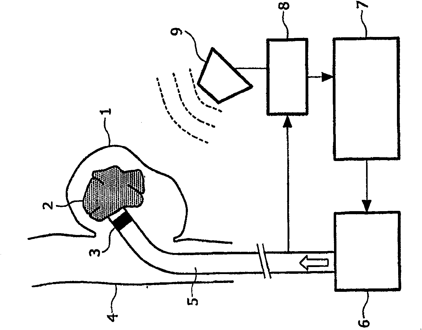
[0033] exist figure 1 As can be seen in the schematic diagram of , during the therapeutic embolization of an aneurysm 1 in the vessel wall 4, a catheter 5 is inserted into the aneurysm. A suitable occluding material 2, such as a curable polymer, may then be injected through the catheter 5 into the aneurysm 1 in order to occlude said aneurysm and terminate its negative impact on blood flow. Plugging material 2 is supplied to conduit 5 by means of controllable pump means 6 .

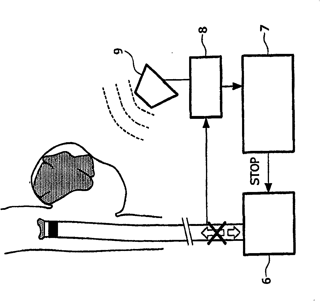
[0034] During the injection of the plugging material 2 , a problem arises that the catheter 5 tends to stretch and thus emerge from the aneurysm 1 . If this happens, the occluding material 2 is injected into the blood stream, which entails the risk of blocking the blood vessel, damaging it or causing fatal embolism (stroke). Extra care is therefore required to ensure that the catheter 5 remains in the aneurysm 1 when embolization is performed.

[0035]The use of the device shown in the accompanying draw...


PUM


Abstract

The invention relates to an apparatus and a method for the therapeutic embolization of an aneurysm (1) as well as to a catheter. A plugging material (2) is injected via a catheter (5) inserted into the aneurysm (1). During the injection, the spatial position of an active locator (3), such as a magnetic field sensor for example, which is fitted to the tip of the catheter (5) is observed by a locating device (8, 9). If emergence of the catheter tip from the aneurysm (1) is detected by a monitoring unit (7), said monitoring unit stops the further supply of plugging material to the catheter (5).

Description

technical field [0001] The present invention relates to catheters, devices and methods for therapeutic embolization of aneurysms using catheters. Background technique [0002] In therapeutic embolization of aneurysms, the negative effects of aneurysms on blood flow are inhibited by injecting suitable occlusive materials to eliminate cavities caused by disturbances in the vasculature. Many variants of therapeutic embolization are known from the literature. For example, US 6024754 describes the combination of a coil first inserted into the aneurysm with a curable polymer subsequently introduced. An x-ray opaque marker is mounted on the tip of the associated catheter so that its position can be determined on the x-ray image. Furthermore, US 6024754 states that during injection of occluding material into an aneurysm, it is known to require care not to protrude the tip of the catheter from the aneurysm and discharge the occluding material into the blood stream or block the vess...

Claims


Application Information

Patent Timeline
Patent Type & Authority Patents(China)
IPC IPC(8): A61B17/12A61B19/00
CPCA61B17/12186A61B2019/5251A61B19/5244A61B17/12195A61B17/12113A61B17/12022A61B2017/1205A61B34/20A61B2034/2051
Inventor J·博尔格特D·M·巴比克
Owner KONINK PHILIPS ELECTRONICS NV
Why Eureka
Try Eureka