Pulse injection apparatus

An injection device and pulse technology, which can be used in syringes, auto-injectors, and injectors by means of jetting, etc., can solve the problems of uncontrollable injection depth, difficult implementation, and pain.

Active Publication Date: 2010-02-24
LUOHE SHUGUANG HUIZHIKANG BIOTECH
View PDF5 Cites 1 Cited by
  • Summary
  • Abstract
  • Description
  • Claims
  • Application Information

AI Technical Summary

Problems solved by technology

[0005] There are still many deficiencies in the current jet injection system: (1) The small amount of injection is a common problem of various jet injection drug delivery systems, because the jet injection is only completed in one action, so the general administration volume is 0.1 ~ 1ml , the maximum injection volume in existing products does not exceed 1.5ml, if the injection volume is too large, it will cause severe pain; (2) The injection depth is uncontrollable, so when the injection depth is too deep, the jet touches the nervous system under the skin tissue It will be accompanied by a strong pain. Although the focused multi-nozzle can control the depth in theory, it is difficult to apply in practice due to the difficulty of processing; (3) The injection dose accuracy is poor, and the spring-powered injection The working stability of the syringe is poor, and it is easy to cause the difference in the dosage; (4) the injection release process (speed, frequency) is uncontrollable, because the power source of the syringe compresses the spring or the inherent characteristic parameters of the high-pressure gas (the stiffness of the spring or the pressure of the gas) Pressure) is given by the syringe system itself
Although from the text description of this patent, it has the advantages of convenience, safety, more stable injection flow and speed, easier control, and large injection dose, but it is difficult to implement in the actual application process, and the injection tube takes medicine. inconvenient

Method used


Image

  • Pulse injection apparatus
  • Pulse injection apparatus
  • Pulse injection apparatus

Examples


Embodiment Construction

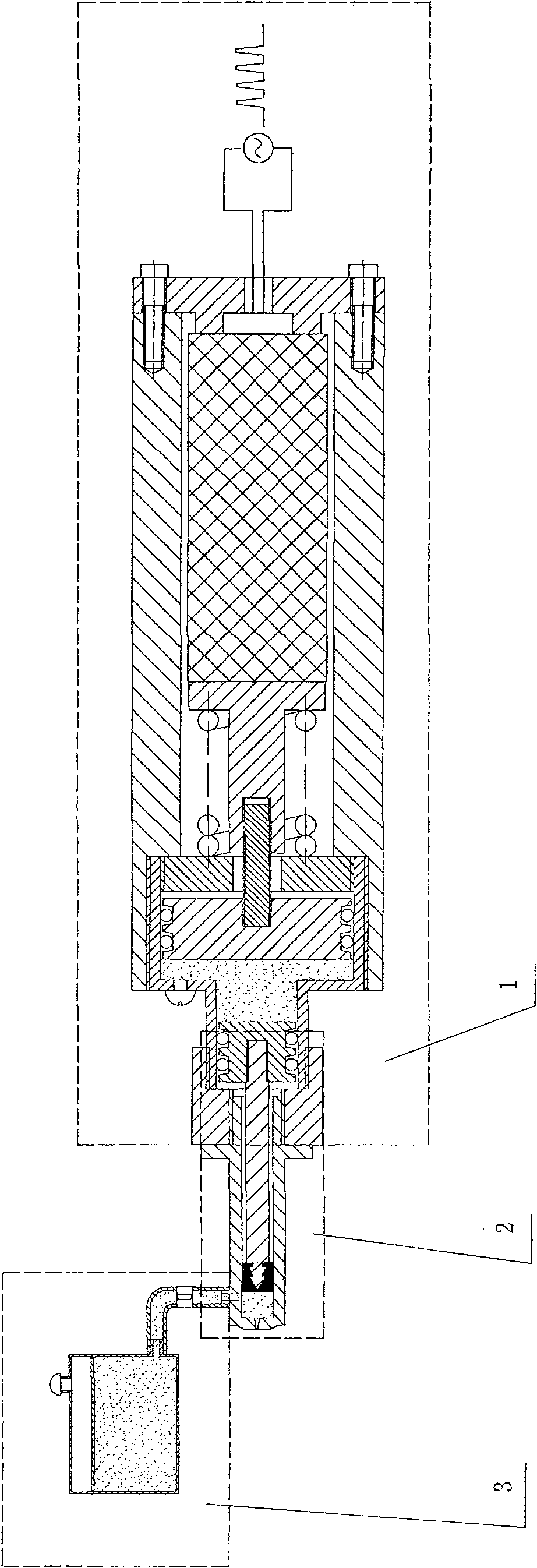
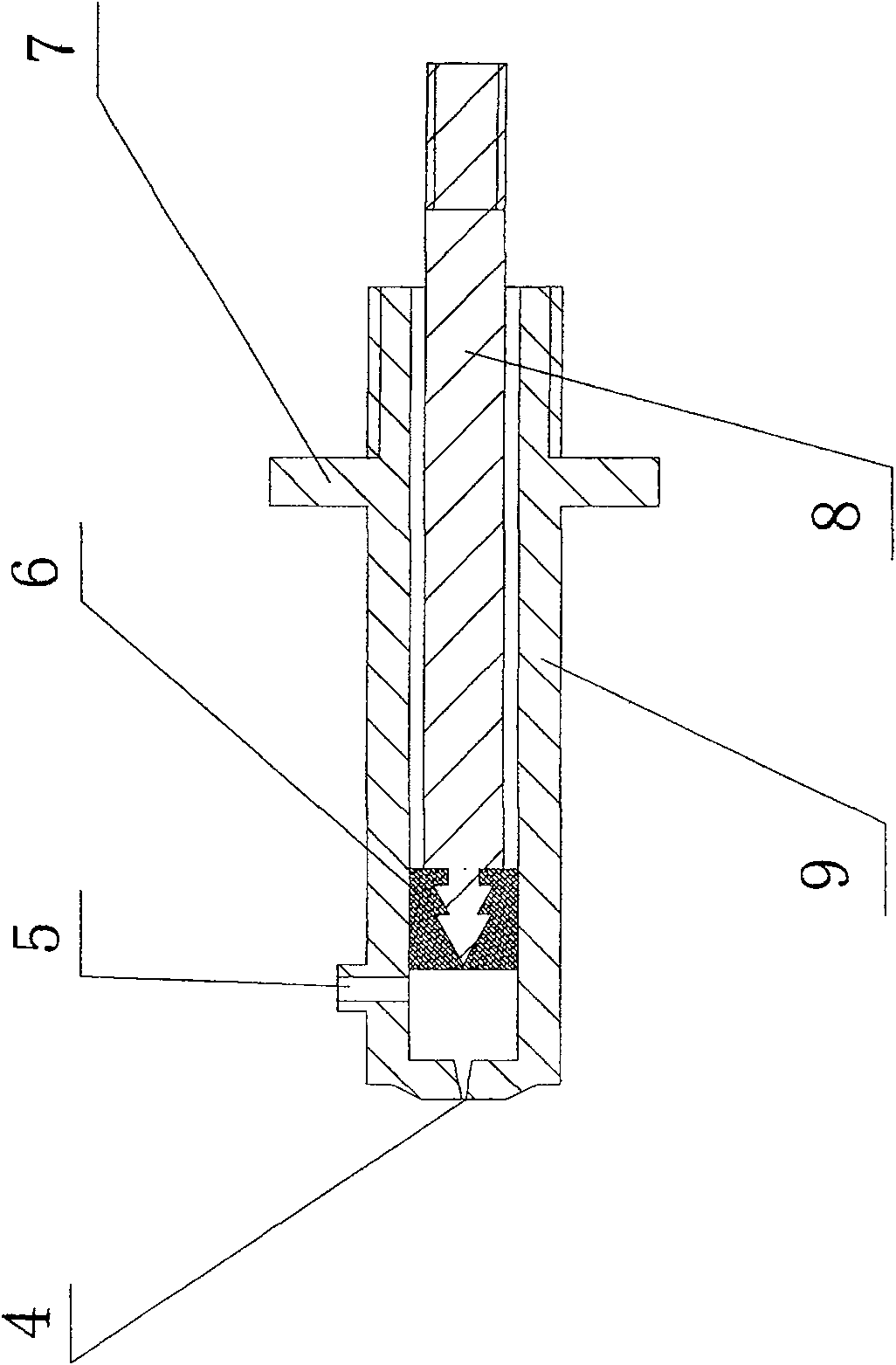
[0027] Such as figure 1 , 2 , 3, 4, and 5, the pulse injection device of the present invention includes an ampoule 2 and a medicine storehouse 3 installed on the front end of the piezoelectric pulse ejection device 1, and the ampoule 2 includes a front end with a micro nozzle hole 4 and an opening at the rear end. A cylinder 9, a push rod 8 with a piston 6 fixed at the front end is movably installed in the cylinder 9, which is a common structure of a pulse injection device.

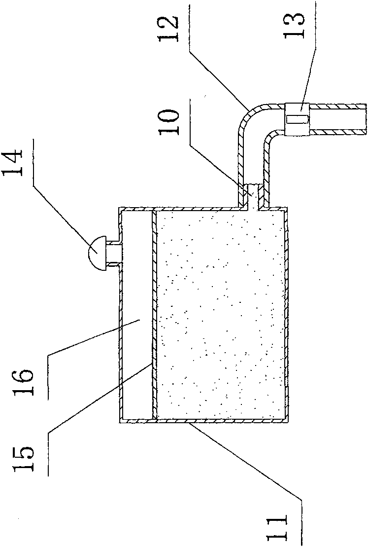
[0028] The improvement of this case is: the front end wall of the cylinder body 9 is provided with an interface 5 communicating with the drug store 3, and the interface 5 is located between the initial position and the maximum stroke of the piston 6, close to the piston 6. For the convenience of socketing, the interface 5 can be designed to be higher than the outer wall of the cylinder 9 . The drug store 3 includes a closed box 11 with a drug outlet 10 , a pressurization system is installed in the box 1...


PUM


Abstract

The invention discloses a pulse injection device which belongs to the technical field of the subcutaneous-administration device in the medical appliance. The pulse injection device comprises an ampoule mounted at the front end of a piezoelectric pulse push shot device and a drug storehouse. The ampoule comprises a cylinder body, wherein a minitype spray orifice is arranged at the front end part ofthe cylinder body, and an opening is arranged at the rear end thereof; a push rod is movably mounted in the cylinder body, and a piston is fixed at the front end of the push rod; and an interface which communicates with the drug storehouse is arranged on the front end wall of the cylinder body, and is positioned between the start position and the maximum stroke of the piston. The drug storehousecomprises a closed-type case body with a drug outlet, and a pressurizing system is mounted in the case body. A hose with a switch is sleeved between the drug outlet and the interface. The pulse injection device has the advantages of convenient drug fetch, high injection dosage, controllable injection depth, high injection dosage precision and controllable injection and drug release process.

Description

technical field [0001] The invention discloses a pulse injection device, which belongs to the technical field of subcutaneous drug delivery devices in medical equipment. Background technique [0002] Transdermal drug delivery system refers to a new dosage form that directly administers drugs on the surface of the skin, allowing the drug to pass through each layer of the skin and enter the systemic circulation to produce systemic or local therapeutic effects. As a non-invasive drug delivery route, the transdermal drug delivery system has obvious advantages, specifically: the drug absorption is not affected by complex factors such as the pH value in the digestive tract, food, and the moving time of the drug in the intestinal tract; The first-pass effect of the drug in the liver; it can produce a sustained, constant and controllable administration rate and blood concentration, reduce the number of administrations and doses, thereby reducing adverse reactions; improve the bioava...

Claims


Application Information

Patent Timeline
Patent Type & Authority Patents(China)
IPC IPC(8): A61M5/30A61M5/20A61M5/31A61M5/178A61M37/00
Inventor 陈凯吕永桂
Owner LUOHE SHUGUANG HUIZHIKANG BIOTECH
Why Eureka
Try Eureka