Composite nozzle for preparing supercritical fluid nanometer micrometer materail
A supercritical fluid, nano-micron technology, applied in the direction of spraying device, spraying device, liquid into beads and granulation, etc., can solve the problems of low efficiency and complicated operation, and achieve the effect of fast adjustment, small size and high adjustment efficiency
- Summary
- Abstract
- Description
- Claims
- Application Information
AI Technical Summary
Problems solved by technology
Method used
Image
Examples
Embodiment 1
[0037] 1. Embodiment 1: Select basic components to assemble a three-channel internal mixing nozzle.
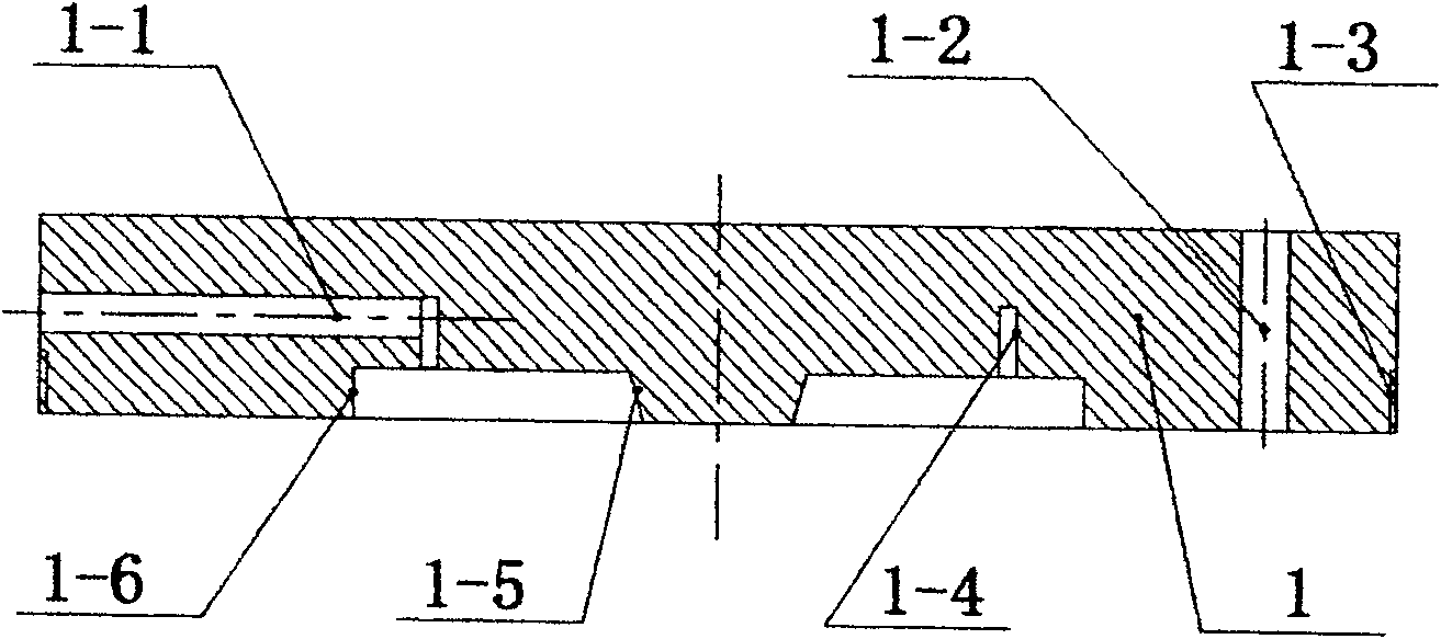
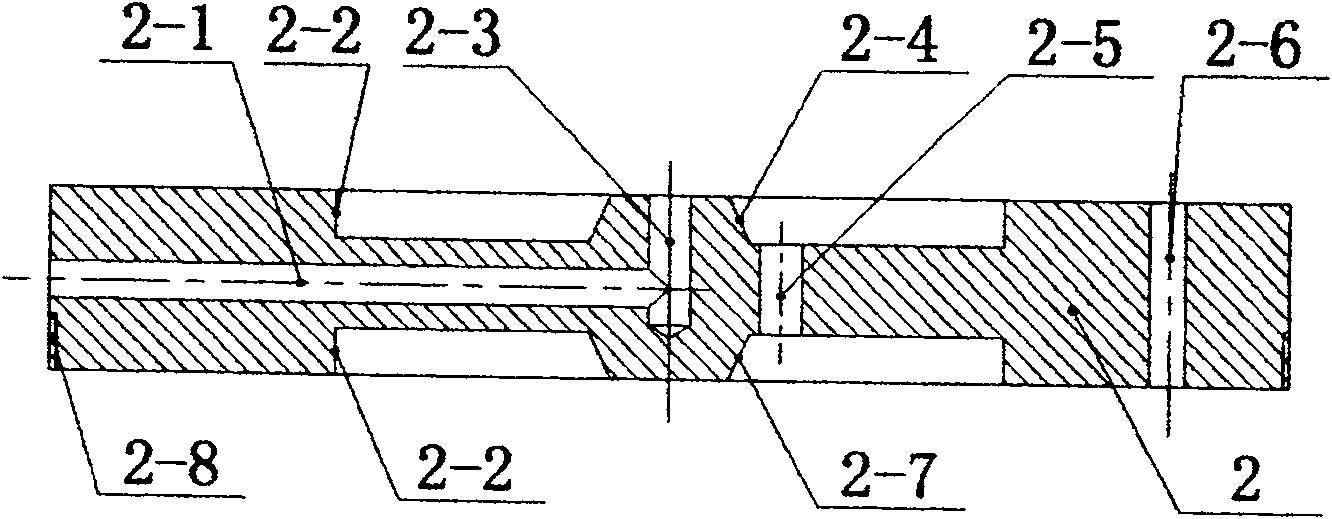
[0038] Such as Figure 5 As shown, select an end cover 1, two internal mixing rings 2 and three moving rings 4, and assemble with a crystallizer 9. The installation process is:
[0039]The adjustment thread 4-5 of the first moving ring 4 is installed with the adjustment nut 5, and the upper side of the adjustment nut 5 is screwed into the adjustment thread 1-3 on the end cover 1, and the direction of rotation of the adjustment thread 1-3 is the same as that of the adjustment thread 4-5. The direction of rotation is opposite, the adjusting nut 5 rotates left and right, and at the same time, the sub-port 1-6 of the end cover 1 is installed together with the upper side boss 4-2 of the moving ring 4, and the sealing ring 7 is installed in the sealing groove 4-1; the moving ring 4 The lower side boss 4-2 of the first internal mixing static ring 2 is installed together with the up...
Embodiment 2
[0047] 2. Embodiment 2: Select basic components to assemble a four-channel external mixing nozzle.
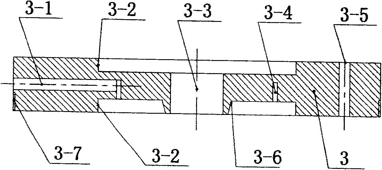
[0048] Such as Figure 6 As shown, select one end cover 1, three outer mixing static rings 3 and four moving rings 4, and assemble with one crystallizer 9. The installation process is:
[0049] Install the adjustment nut 5 on the adjustment thread 4-5 of the first moving ring 4, screw the adjustment thread 1-3 on the end cover 1 into the other side of the adjustment nut 5, and adjust the direction of rotation and adjustment of the adjustment thread 1-3. The thread 4-5 rotates in the opposite direction, and the adjusting nut 5 rotates left and right. At the same time, the sub-port 1-6 of the end cover 1 is installed together with the upper boss 4-2 of the moving ring 4, and a sealing ring is installed in the sealing groove 4-1. 7; The lower side boss 4-2 of the moving ring 4 is installed together with the upper side sub-port 3-2 of the first outer mixed static ring 3, and the ...
Embodiment 3
[0055] 3. Embodiment 3: Select basic components to assemble a four-channel internal and external mixing nozzle.
[0056] Such as Figure 7 As shown, select one end cover 1, one inner mixing static ring 2, two outer mixing static rings 3, four moving rings 4, and assemble with a crystallizer 9. The installation process is:
[0057] The adjustment thread 4-5 of the first moving ring 4 is equipped with an adjustment nut 5, which is screwed into the adjustment thread 1-3 of the end cover 1. The direction of rotation of the adjustment thread 1-3 is opposite to that of the adjustment thread 4-5, and the adjustment nut 5 is Rotate left and right, and at the same time, the sub-port 1-6 of the end cover 1 is installed together with the upper side boss 4-2 of the first moving ring 4, and the sealing ring 7 is installed in the sealing groove 4-1; the lower side boss of the moving ring 4 4-2 is installed together with the upper sub-port 2-2 of the inner mixing static ring 2, the center ...
PUM
 Abstract
Description
Claims
Application Information
 - R&D
- Intellectual Property
- Life Sciences
- Materials
- Tech Scout
- Unparalleled Data Quality
- Higher Quality Content
- 60% Fewer Hallucinations
Browse by: Latest US Patents, China's latest patents, Technical Efficacy Thesaurus, Application Domain, Technology Topic, Popular Technical Reports.
© 2025 PatSnap. All rights reserved.Legal|Privacy policy|Modern Slavery Act Transparency Statement|Sitemap|About US| Contact US: help@patsnap.com


