Node of steel tube concrete pole and steel reinforced concrete beam and processing method thereof

A technology for reinforced concrete beams and CFST columns, which is applied to the joint structure of CFST columns and reinforced concrete beams and their construction fields, can solve problems such as the inability to adopt the joint form with ring beams, reduce welding workload, and ensure welding The effect of seam quality and convenient construction

Inactive Publication Date: 2007-07-18
SOUTH CHINA UNIV OF TECH
View PDF0 Cites 16 Cited by
  • Summary
  • Abstract
  • Description
  • Claims
  • Application Information

AI Technical Summary

Problems solved by technology

However, under the requirements of most architectural and decorative designs, the joint form with ring beams cannot b

Method used


Image

  • Node of steel tube concrete pole and steel reinforced concrete beam and processing method thereof
  • Node of steel tube concrete pole and steel reinforced concrete beam and processing method thereof
  • Node of steel tube concrete pole and steel reinforced concrete beam and processing method thereof

Examples


Embodiment Construction

[0024] The present invention will be described in further detail below with reference to the accompanying drawings and examples, but the embodiments of the present invention are not limited thereto.

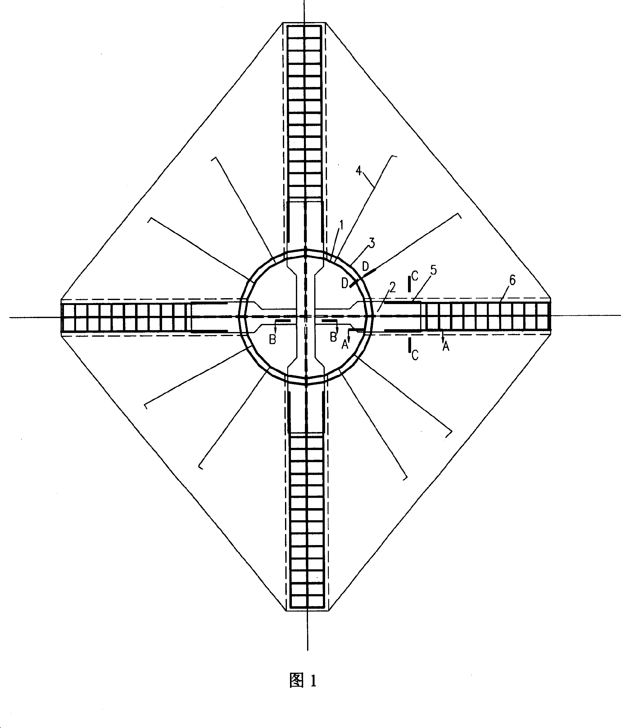
[0025] Fig. 1 is the specific structural diagram of the joint structure of the concrete-filled steel pipe column and the reinforced concrete beam. 4. Beam main reinforcement thread sleeve 5, beam main reinforcement 6. 4 I-shaped dark piercing steel corbels 2 pass through the steel pipe 1 and intersect and weld in the pipe, the ring reinforcement 3 is welded on the upper flange of the steel corbel 2, and 7 plates The surface radial ribs 4 are evenly distributed between the beams and extend to the bottom of the floor slab; the double-sided fillet welds of the threaded sleeve 5 are welded to the flange at the upper end of the steel corbel, and are on a straight line with the main ribs 6 of the beam.

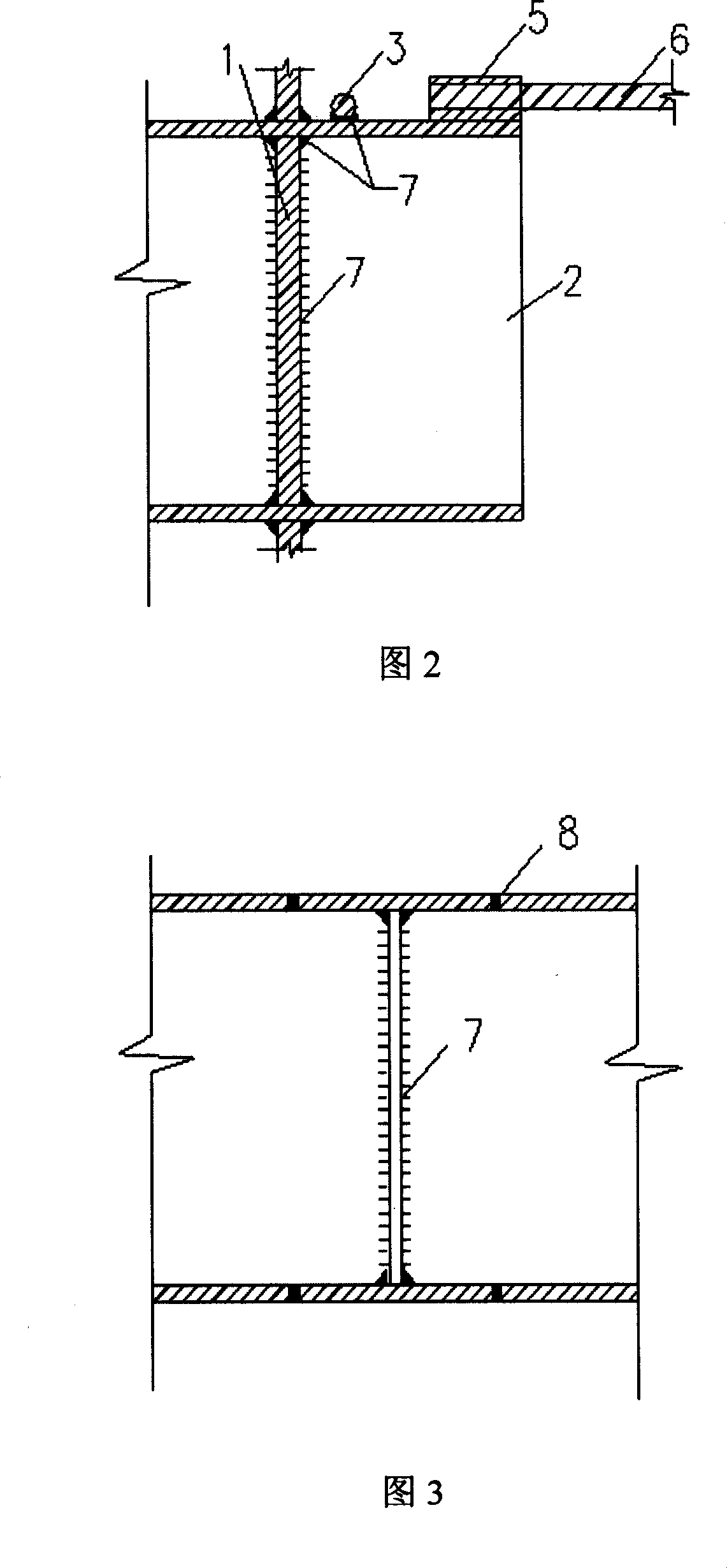
[0026] Fig. 2 is a cross-sectional view of the connection relationship between the...


PUM


Abstract

The present invention discloses one kind of node structure for steel core concrete column and reinforced concrete beam and its forming process. The node structure includes feed-through bracket penetrating through and welded to steel pipe, ring rib welded to steel bracket outside the steel pipe, plate radial rib bent and hooked to the ring rib and main spiral rib sleeve welded to the end of the steel bracket. The forming process of the node structure includes calculating size of steel bracket, determining radial rib number and diameter and ring rib diameter, welding in plant, in-site tying of steel bars, and pouring concrete. The node structure has determined force transfer, capacity of controlling the crack development effectively, convenient construction and excellent engineering application foreground.

Description

technical field [0001] The invention relates to the field of structural engineering in civil engineering, in particular to a joint structure of a steel pipe concrete column and a reinforced concrete beam and a construction method thereof. Background technique [0002] Since the mid-1960s, CFST has been introduced into my country, and has been widely used in the construction of high-rise and super high-rise buildings and long-span bridges due to its superior mechanical properties. On the one hand, due to the restraining effect of the steel pipe on the filled concrete, the concrete is in a stress state of three-dimensional compression, so that its compressive strength can be fully exerted; on the other hand, due to the filling effect of the concrete, the buckling resistance of the steel pipe under the action of axial force is improved. ability. This very reasonable material combination of steel tube concrete structure can give full play to and utilize the characteristics of s...

Claims


Application Information

Patent Timeline
IPC IPC(8): E04B1/19E04B1/21E04B1/30E04B1/58
Inventor 韩小雷季静郑宜王燕珺
Owner SOUTH CHINA UNIV OF TECH
Why Eureka
Try Eureka