Eureka AIR delivers breakthrough ideas for toughest innovation challenges, trusted by R&D personnel around the world.

Rotor for rotation type displacement pump

A positive displacement pump, rotary technology, applied in the field of positive displacement pumps, can solve the problems that the rotor is easily stuck in the pump body, affects the delivery work of the positive displacement pump, reduces the service life of the positive displacement pump, etc., achieves simple structure, improved service life, and easy processing Effect

Active Publication Date: 2007-07-18
宁波得利时泵业有限公司
View PDF1 Cites 7 Cited by
  • Summary
  • Abstract
  • Description
  • Claims
  • Application Information

AI Technical Summary

Problems solved by technology

[0003] However, in the current rotary positive displacement pump, the rotor generally includes a body with a shaft hole in the center and blades arranged symmetrically to the center of the shaft hole. The number of the blades can be two or three, and some are even more. The shape and size of the end face of the blade are adapted to the inner side of the pump body, that is, the end face is a circular arc surface with a smooth surface. When working, the conveyed medium fills the entire pump cavity, and the space between the end face of the blade and the pump body is also filled with medium. , in the actual use process, the medium to be transported often contains fine particles and uncertain impurities, such as incompletely ground solid particles, hard welding slag in the pipeline, etc., the medium with solid particles will With the rotation of the rotor, the end faces of the blades and the inner side of the pump body are constantly rubbed, so that the parts will wear out over time, reducing the service life of the positive displacement pump, and when encountering that kind of hard welding slag, the rotor is easily stuck in the pump body , which seriously affects the normal conveying work of the positive displacement pump, and the parts are easily damaged.

Method used


Image

  • Rotor for rotation type displacement pump
  • Rotor for rotation type displacement pump

Examples


Embodiment Construction

[0013] The present invention will be further described in detail below in conjunction with the accompanying drawings and embodiments.

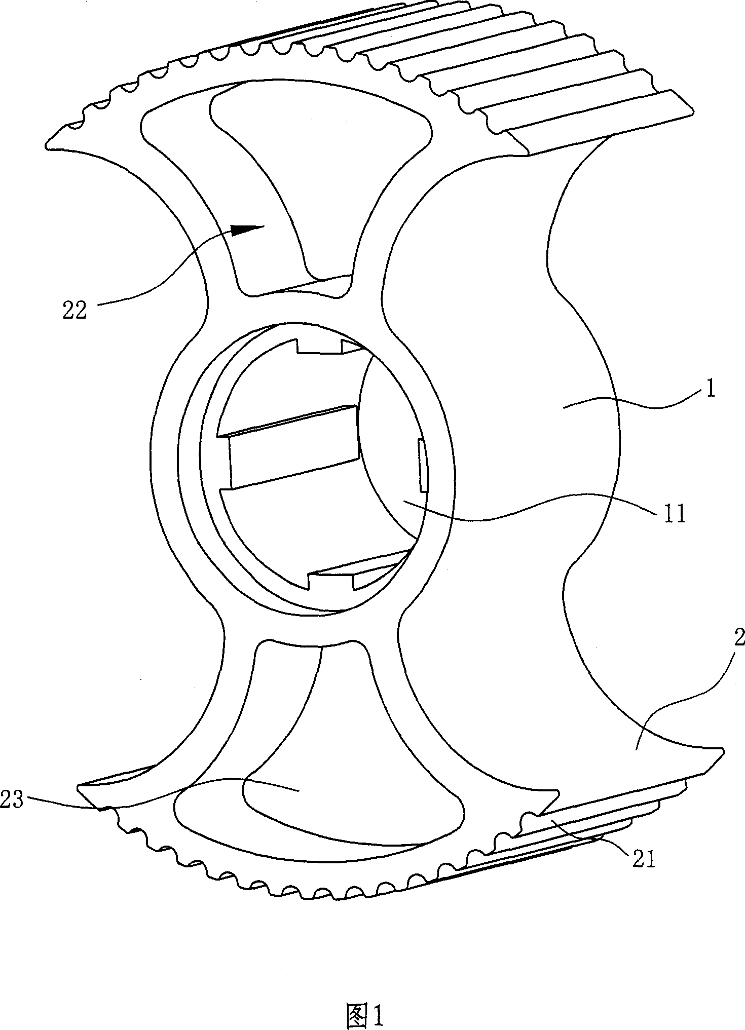
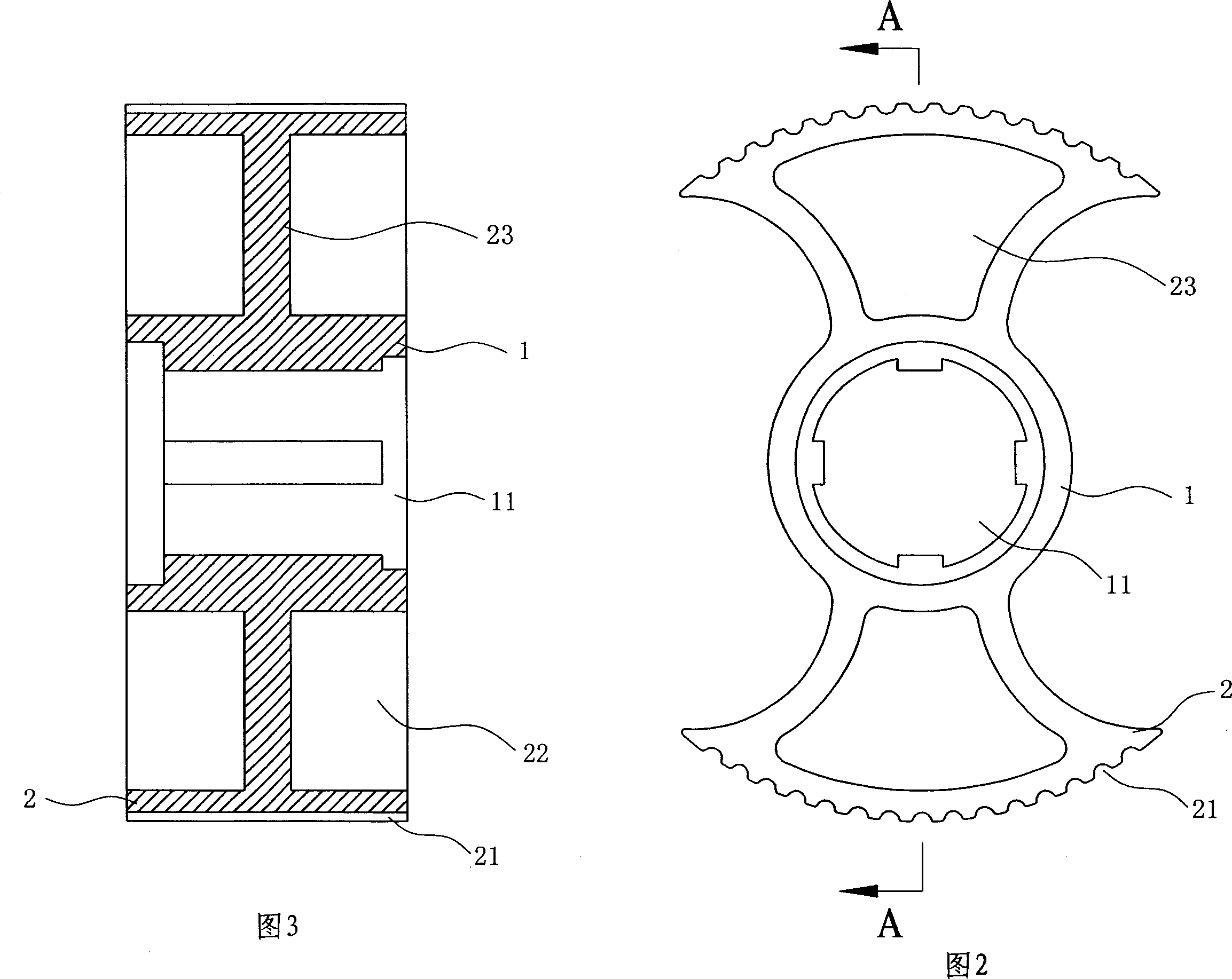
[0014] As shown in Figures 1 to 3, the rotor for a rotary positive displacement pump includes a body 1 with a shaft hole 11 in the center and blades 2 symmetrically centered on the shaft hole 11. In this embodiment The blade 2 is provided with two pieces;

[0015] Wherein, the end surface of the blade 2 is provided with a plurality of grooves 21 parallel to the axial direction of the rotor, and the cross section of the grooves 21 is semicircular;

[0016] Moreover, the blades 2 are provided with concave cavities 22 on both sides tangential to the axial direction of the rotor, and the corresponding concave cavities 22 on both sides cooperate to naturally form a partition wall 23 to separate the blades 2 from front to back. .

[0017] When working, the rotor is driven by the main shaft pierced in the shaft hole 11, and rotates in the pump body...


PUM


Abstract

The rotor for rotary displacement pump includes one main body with central shaft hole and blades set symmetrically around the shaft hole. The blade has groove parallel to the rotor axis in the end and cavities in the two-side tangent to the rotor axis. In case that t some granular or hard impurity passes through the end of the blade, the impurity can crush into the groove to avoid jamming of and friction to the blade, and this can ensure the fluent conveyance of medium and increase the service life of the rotor pump.

Description

technical field [0001] The invention relates to the technical field of displacement pumps, in particular to a rotor for a rotary displacement pump. Background technique [0002] Positive displacement pumps have been widely used in chemical industry, metallurgy, electric power, papermaking, food, pharmaceuticals, synthetic fibers and other industrial sectors. Positive displacement pumps are divided into two categories: reciprocating and rotary. Viscous high-concentration media, corrosive media, or media that do not allow contamination, such as lubricating fluid, chocolate pulp, paper pulp, etc. The existing rotary positive displacement pump generally includes a pump body with an inlet and outlet, a pump cover, a main shaft, a driven shaft, two rotors in the pump body that are eccentric to each other and arranged crosswise, transmission parts and mechanical seal parts, wherein the main shaft The driven shaft and the driven shaft drive the two rotors to rotate oppositely to ea...

Claims


Application Information

Patent Timeline
IPC IPC(8): F04C2/14F04C15/00
Inventor 聂如国
Owner 宁波得利时泵业有限公司
Why Eureka
Eureka Blog
Learn More