Charge-discharge controller for solar lighting equipment

A charge and discharge control, lighting equipment technology, applied in lighting devices, circuit devices, battery circuit devices, etc., can solve the problem that solar energy cannot be fully utilized.

Inactive Publication Date: 2007-07-18
ADDA
View PDF0 Cites 0 Cited by
  • Summary
  • Abstract
  • Description
  • Claims
  • Application Information

AI Technical Summary

Problems solved by technology

[0012] For this reason, the main purpose of the present invention is to provide a new charging and discharging control device for solar lighting equipment, to solve the problem that solar energy cannot be fully utilized

Method used


Image

  • Charge-discharge controller for solar lighting equipment
  • Charge-discharge controller for solar lighting equipment
  • Charge-discharge controller for solar lighting equipment

Examples


Embodiment Construction

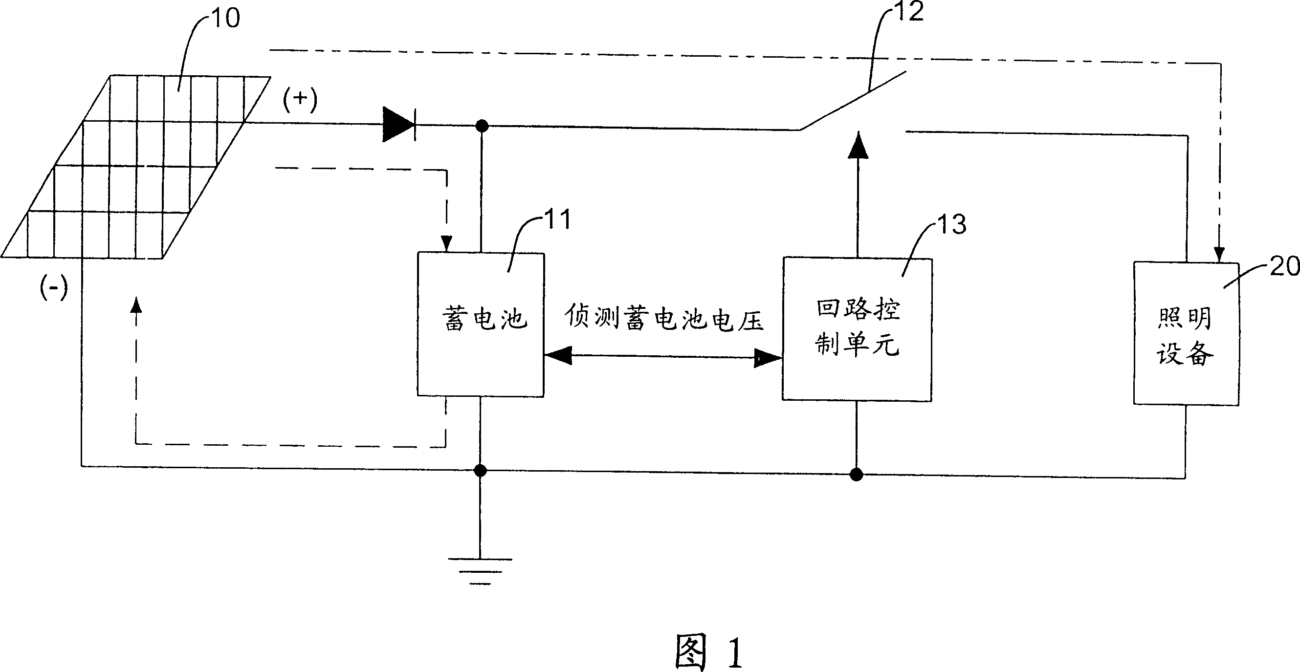
[0025] First please refer to Fig. 1, which is a structural diagram of the charging and discharging control device of the solar lighting equipment of the present invention, which mainly includes:

[0026] A solar panel group 10, which converts solar light into DC power, includes a high potential terminal (+) and a low potential terminal (-);

[0027] A storage battery 11, one end of which is connected to the high potential end (+) of the solar panel group 10 through a diode D1, and the other end is connected to the low potential end (-) of the solar panel group 10;

[0028] A lighting device 20, which is connected to both ends of the battery 11, and when the lighting device 20 is started, the battery 11 provides power for the lighting device;

[0029] A circuit switch 12, connected to the power supply circuit between the storage battery 11 and the lighting equipment 20; the circuit switch 12 can be a transistor or a metal field effect transistor;

[0030] The primary loop cont...


PUM


Abstract

The invention relates to a charging and discharging control device for solar lighting equipments, which is mainly composed of solar panels, a storage battery and lighting equipment. The described parts are paralleled together. A loop switch is installed on the power-loop between the storage battery and the lighting equipment. A controlling unit controls the loop switch to open or close which connects to the storage battery to detect the power level of the battery and takes it as the basis for the loop switch. When the battery is sufficient, the loop switch of the controlling unit is open, so batteries and solar panels provide lighting equipments.

Description

technical field [0001] The invention relates to a charge and discharge control device for solar lighting equipment, in particular to a charge and discharge control device that can effectively reduce production costs and is easy to produce in batches. Background technique [0002] With the advancement of human science and technology, energy consumption has increased. Currently, fossil fuels are the main energy source, but limited oil energy may cause energy crises in the future. Therefore, countries are currently actively developing and utilizing natural phenomenon energy to alleviate the unpredictable crisis caused by the depletion of oil in the future. [0003] Although there is still nuclear energy as a large amount of power generation energy, nuclear energy and its waste have dangerous radiation that can harm the human body, and have been banned by some countries. Therefore, among the natural power sources that are currently being studied, the research on solar energy sy...

Claims


Application Information

Patent Timeline
Patent Type & Authority Applications(China)
IPC IPC(8): H02J7/35H05B37/00
Inventor 谢新茂
Owner ADDA
Why Eureka
Try Eureka