Driving plan of parallel multi-section contactless switch speed regulating machine

A non-contact switch and speed-regulating motor technology, applied in the electromechanical field, can solve the problems of low reliability of contact relays, affect system reliability, increase heat generation, etc., and achieve the effects of high cost performance, high reliability and high power factor.

Inactive Publication Date: 2007-07-18
苏州扬名机电有限公司 +1
View PDF0 Cites 6 Cited by
  • Summary
  • Abstract
  • Description
  • Claims
  • Application Information

AI Technical Summary

Problems solved by technology

[0003] The reliability of the contact relay is low, and the non-contact relay series connection scheme adds the voltage drop of the electronic relay. In the case of low voltage and high current, it will increase heat generation, reduce efficiency, and affect system reliability.

Method used


Image

  • Driving plan of parallel multi-section contactless switch speed regulating machine

Examples


Embodiment Construction

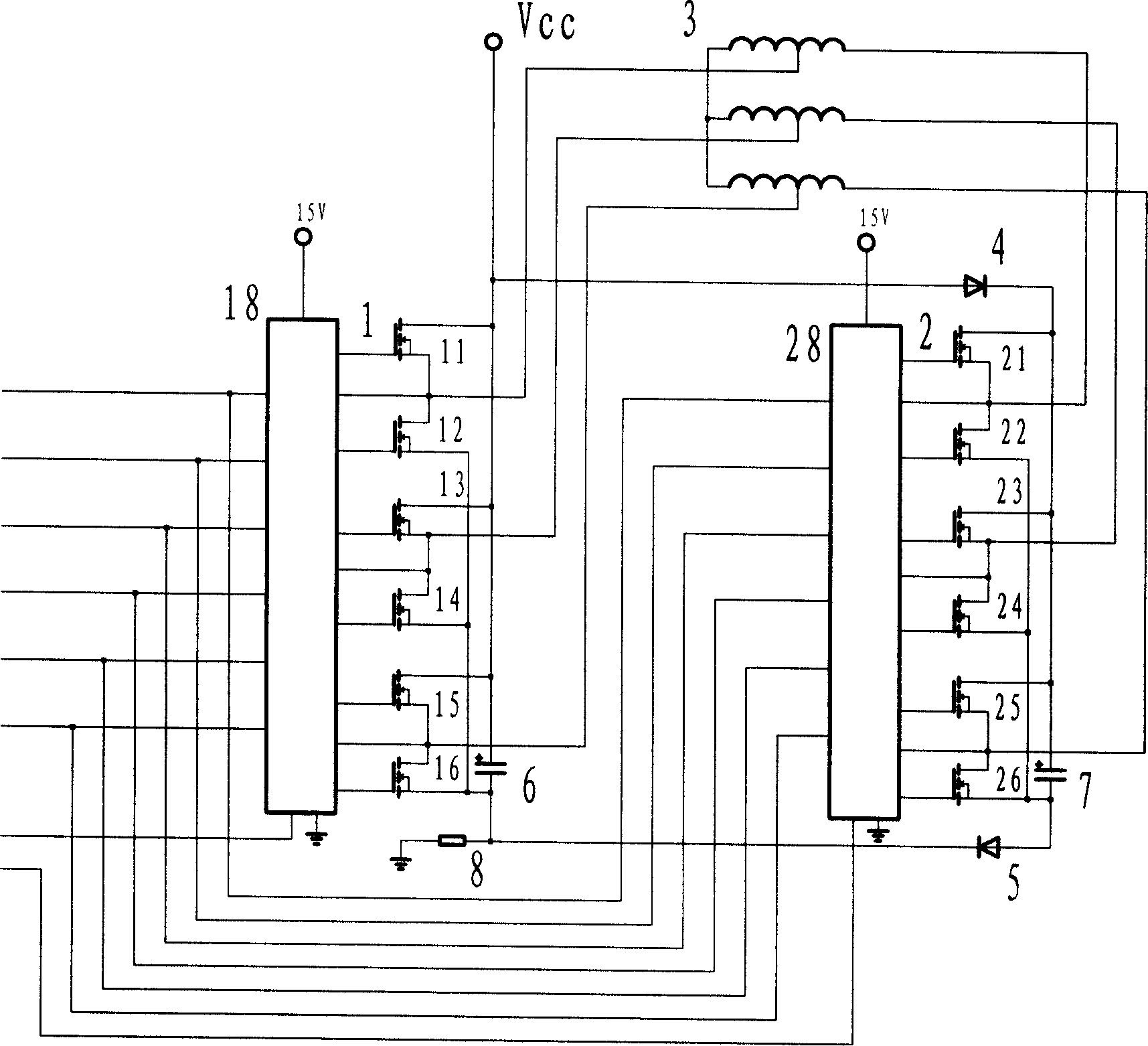
[0014] The technical scheme of the parallel multi-stage non-contact switch speed-regulating motor drive system is described in detail below through illustrations. This embodiment takes a dual-speed (also known as dual-power) three-phase brushless DC motor parallel connection high and low two-stage non-contact power drive scheme as an example.

[0015] With reference to the accompanying drawings: the motor winding 3 is a type with taps for each phase, and high and low speeds respectively have a set of drive circuits 1 and 2, which are composed of 11-16 and 22-26 respectively. When the motor system starts at low speed, the control circuit selects the pre-drive chip 28 through the chip select port, the low-speed drive circuit 2 is powered, and all windings of the drive motor work. After the motor speed is increased to a certain value, the control circuit makes the chip 28 quit working by the chip selection circuit, and simultaneously selects the high-speed pre-drive circuit 18 to...


PUM


Abstract

This invention relates to a drive plan for parallel multi-section contactless switch timing motors composed of a motor with tap to each phase winding, a position sensor, a control circuit and a switch driving circuit characterizing in applying more than two sets of independent power driving circuits parallel to related motor windings, each set of power driving circuits works independently in turn in its related speed region , which is especially used in the hub motor driving system of multi-power electromotive cars and double timing driving system of washing machines and motor driving systems of other industrial wide speed motors.

Description

Technical field: [0001] The invention belongs to the electromechanical field, and in particular relates to an improvement of a driving scheme of an electronic switch speed-regulating motor, especially a driving scheme of a parallel-connected multi-stage non-contact switch speed-regulating motor. Background technique: [0002] The existing commonly used speed control motor systems include: asynchronous motor frequency conversion speed control system, permanent magnet brushless DC motor, switch bias motor system, etc., collectively referred to as electronic switch speed control motor system. In order to further expand the speed regulation range of the motor under limited voltage and current conditions, a motor speed regulation scheme with multiple taps for each phase of high, medium and low is proposed by modifying the motor windings, commonly known as a multi-power switch speed regulation motor. Taking a two-speed motor with one tap per phase as an example, generally multiple...

Claims


Application Information

Patent Timeline
Patent Type & Authority Applications(China)
IPC IPC(8): H02P6/00H02P6/08H02P25/18
Inventor 朱正风
Owner 苏州扬名机电有限公司
Why Eureka
Try Eureka