Underwater propelling plant imitating hydrofoil

A technology of propulsion device and hydrofoil, applied in the field of underwater power propulsion device, can solve problems such as immaturity of power drive research, and achieve the effect of compact structure and convenient installation.

Inactive Publication Date: 2007-07-25
HARBIN ENG UNIV
View PDF0 Cites 35 Cited by
  • Summary
  • Abstract
  • Description
  • Claims
  • Application Information

AI Technical Summary

Problems solved by technology

[0004] In the study of underwater micro-carriers, the research on the application of non-traditional propulsion power is still immature

Method used


Image

  • Underwater propelling plant imitating hydrofoil
  • Underwater propelling plant imitating hydrofoil

Examples


Embodiment 1

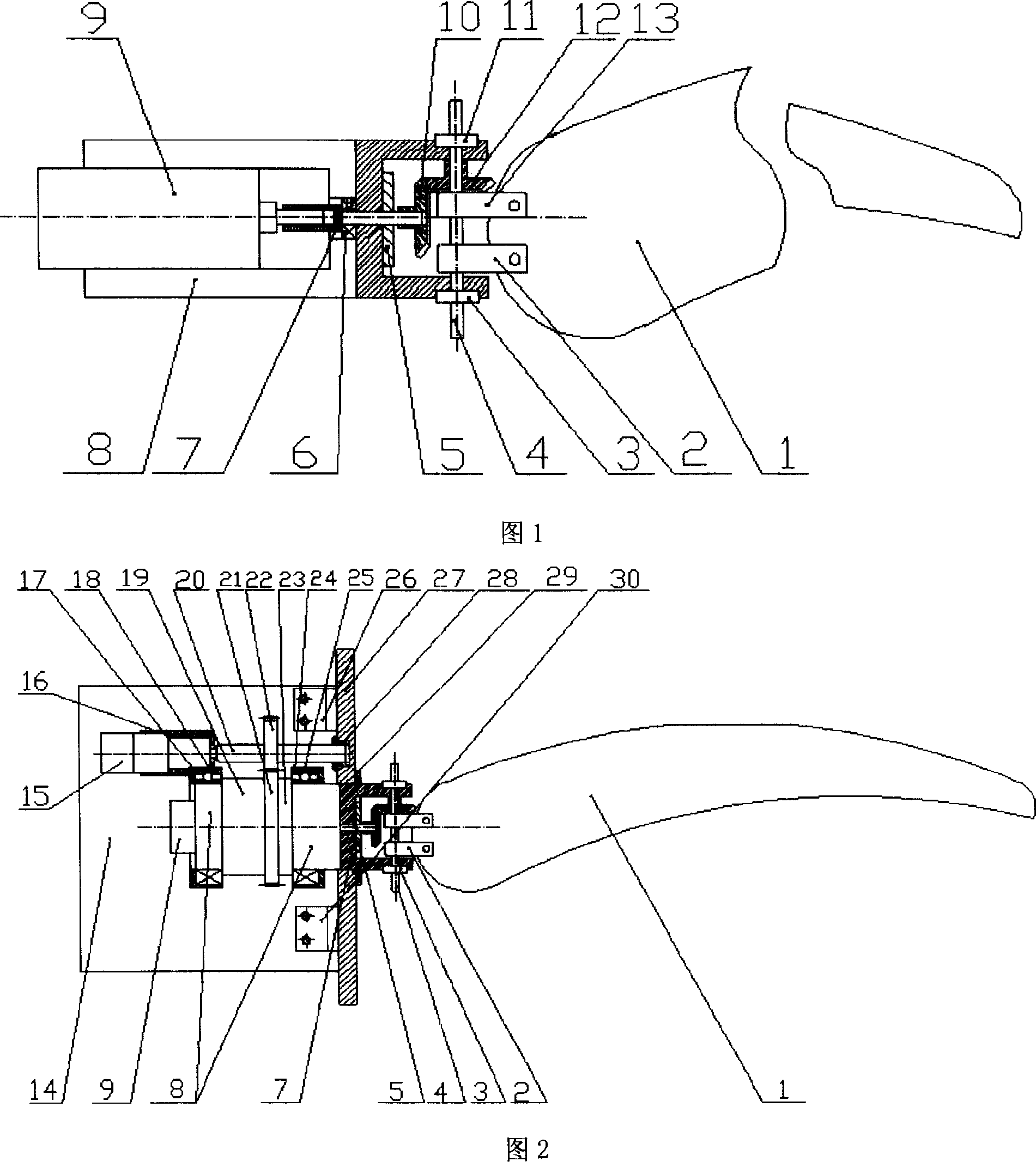
[0020] With reference to Figure 1, the invention includes a bionic hydrofoil, a hydrofoil flapping unit, a hydrofoil rotating unit and a bottom plate fixing unit. The bionic hydrofoil is installed on the hydrofoil flapping unit, and the hydrofoil flapping unit and the hydrofoil rotating unit Connected together, and these two motion units must be installed on the bottom plate fixing unit. The bionic hydrofoil is a hydrofoil model imitating an animal hydrofoil, which includes a hydrofoil model 1 or a hydrofoil model 31 installed on a hydrofoil flapping unit; the hydrofoil flapping unit is composed of a servo motor 9 and a motor sleeve. The cylinder 8, the motor shaft sleeve 7, the small bearing 6, the small bearing 3, the small bearing 11, the seal 5, the bevel gear 10, the bevel gear 12, the small shaft 4, the hydrofoil connector 2 and the hydrofoil connector 13, servo The motor 9 is fixed and enclosed in the motor sleeve 8. The output shaft is connected with the rear end of the mo...

Embodiment 2

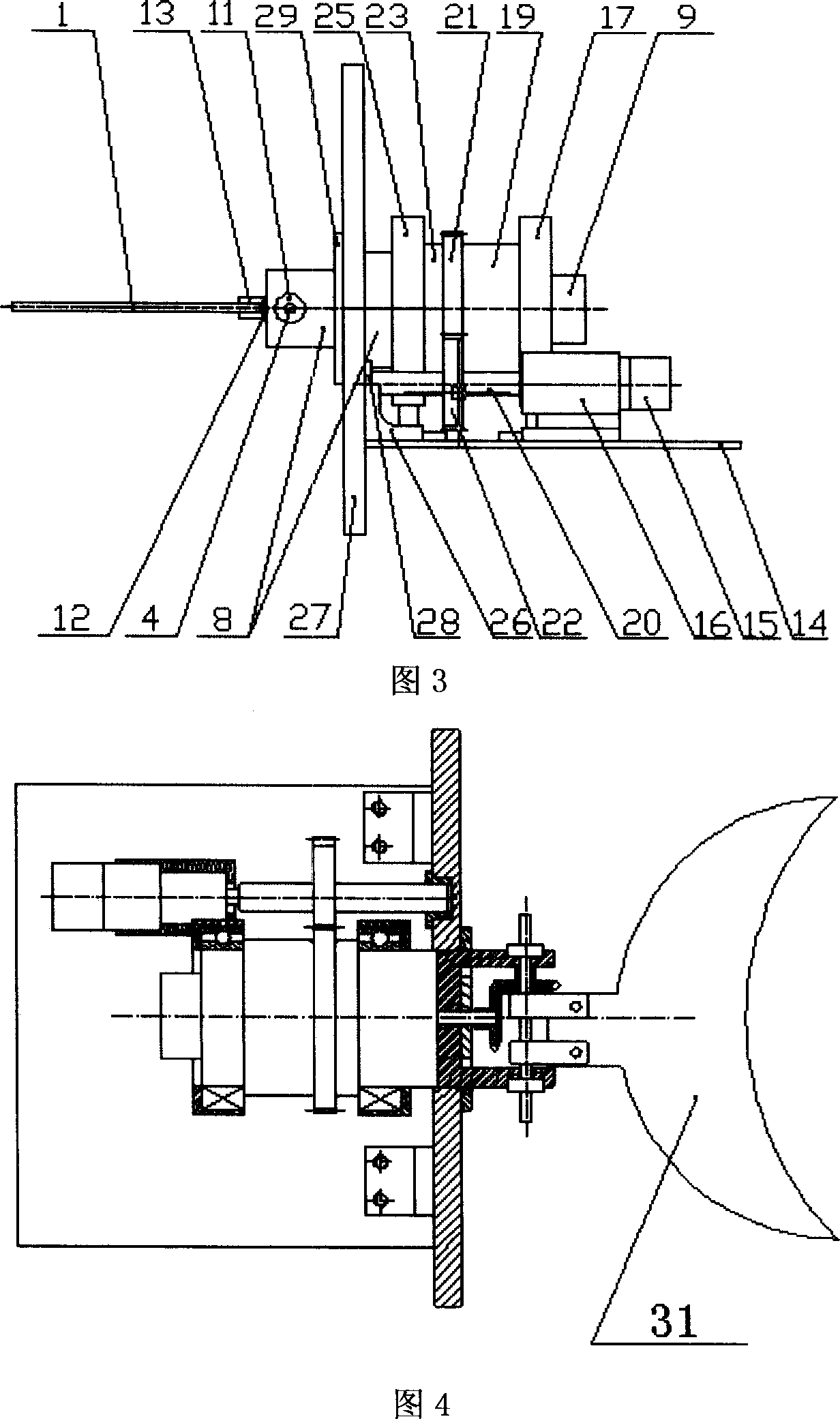
[0023] With reference to Figure 4, the basic structure of this embodiment is the same as that of Example 1, except that the hydrofoil model 31 shown in Figure 4 is used instead of the hydrofoil model 1 in Figure 2 and the device is installed on the tail of the submersible, as shown in the figure The hydrofoil model 31 shown in 4 is behind the wall plate 27 and is in the water; the motor 9 and the motor 15 are in front of the wall plate 27 and are inside the submersible. At this time, the moving direction of the submersible should point to the left side of the drawing. In the state shown in Fig. 4, the motor 15 remains stationary, and the motor 9 performs a forward and reverse movement at a certain angle after starting, so that the hydrofoil model 31 reciprocates around the axis of the small shaft 4. Because the fish-tail fin-shaped hydrofoil model 31 is used instead of the paddle-shaped hydrofoil model 1 in Scheme 1, the motion of the hydrofoil model 31 at this time is somewhat si...


PUM


Abstract

An underwater propeller simulating hydrovane for the underwater self-propulsion vehicle is composed of a bionic hydrovane simulating the fin, a swing unit for said hydrovane, a rotating unit for said hydrovane, and a fixing unit of baseplate for fixing said swing unit and rotating unit to baseplate.

Description

(1) Technical field [0001] The invention relates to the field of underwater bionics, and specifically to an underwater power propulsion device. (2) Background technology [0002] At present, there are many types of underwater propulsion methods applied to underwater vehicles such as submersibles and underwater robots. Among them, the traditional propulsion method is mainly propeller propulsion, and the ability of aquatic animals after a long period of survival of the fittest in swimming and attitude control It is unmatched by current submersible vehicles equipped with traditional propulsion systems. The propulsion methods of aquatic animals can be roughly divided into four categories: swing method, stroke method, hydrofoil method, and jet method. Nowadays, the main research hotspots at home and abroad are concentrated on the representative animal fish propelled by the imitation swing method, and few other swimming the way. The research object created by the present invention is t...

Claims


Application Information

Patent Timeline
Patent Type & Authority Applications(China)
IPC IPC(8): B63H1/36
Inventor 张铭钧储定慧刘晓白窦普齐军赵文德
Owner HARBIN ENG UNIV
Why Eureka
Try Eureka