
Method for establishing radio sensor network rout ebased on route neighbour list

A technology of wireless sensors and neighbor tables, applied in data exchange networks, transmission systems, digital transmission systems, etc., can solve the problems of not supporting node movement, excessive overhead, and only supporting small-scale networks, etc., to solve unstable performance, The effect of small routing overhead and improved stability

Active Publication Date: 2007-07-25
INST OF COMPUTING TECH CHINESE ACAD OF SCI
View PDF0 Cites 39 Cited by
  • Summary
  • Abstract
  • Description
  • Claims
  • Application Information

AI Technical Summary

Problems solved by technology

[0008] In view of this, the main purpose of the present invention is to provide a method for establishing wireless sensor network routing based on the routing neighbor table, to solve the problems that the traditional wireless sensor network routing method has too much overhead, does not support node mobility and only supports small-scale networks

Method used


Image

  • Method for establishing radio sensor network rout ebased on route neighbour list
  • Method for establishing radio sensor network rout ebased on route neighbour list

Examples


Embodiment

[0095] The invention provides a method for establishing a wireless sensor network route based on a routing neighbor table. Only nodes running the protocol are randomly distributed in concerned areas, and the nodes can automatically operate and establish a network.

[0096] It should be noted that the ID numbers of these nodes scattered in an area cannot be the same, and at the same time, it is necessary to ensure that the amount of information in the network cannot exceed the effective bandwidth supported by the nodes, which can be achieved by limiting the number of nodes. When these tasks are completed, the data of each node can be received at the sink node.

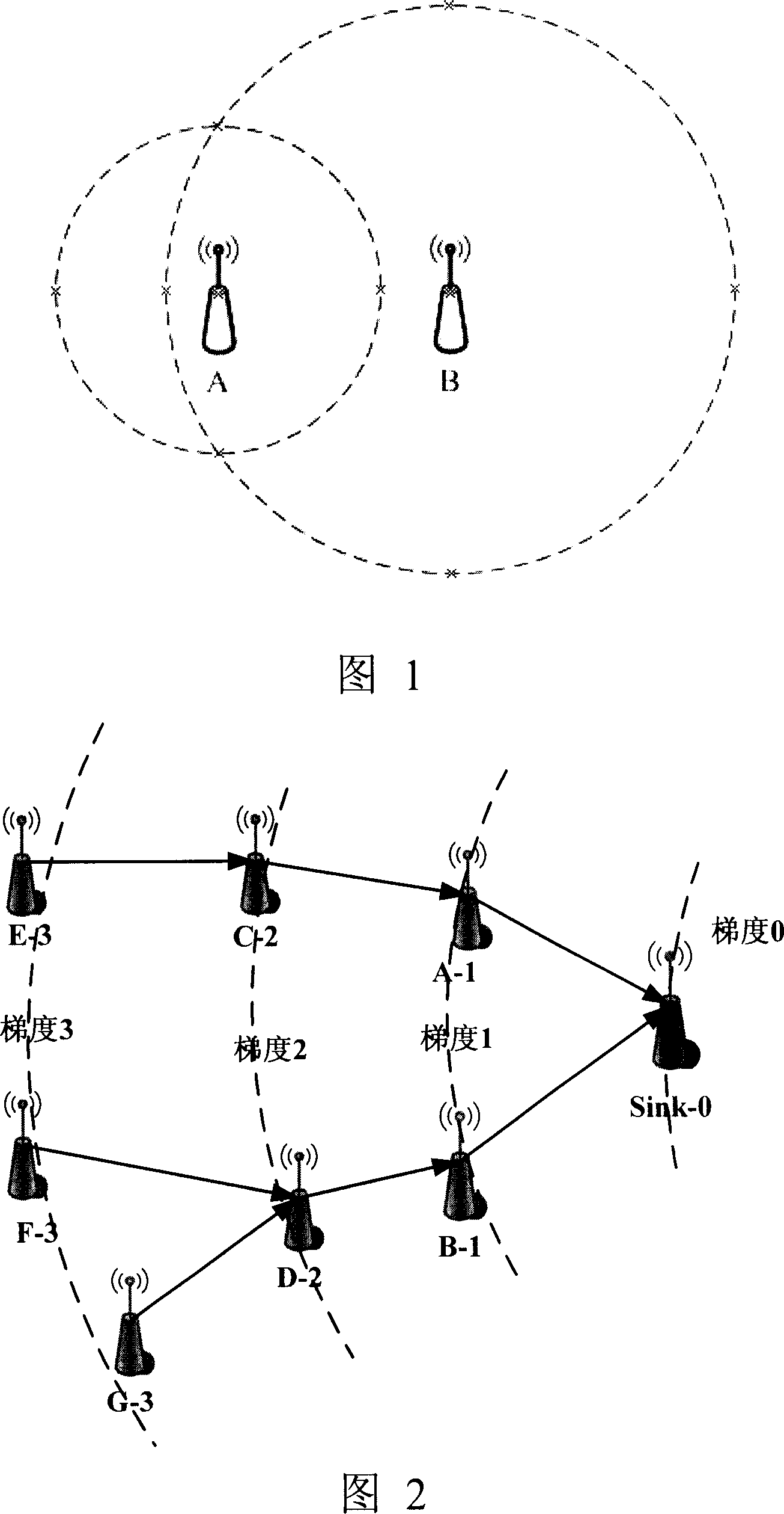
[0097] In the present embodiment, the operation process of the network routing method is introduced in detail with the network composed of 8 nodes described in Fig. 2:

[0098] 1. Turn on all 8 nodes, put the sink node in the designated location (usually the user control room), and randomly distribute the other 7 nodes ...


PUM


Abstract

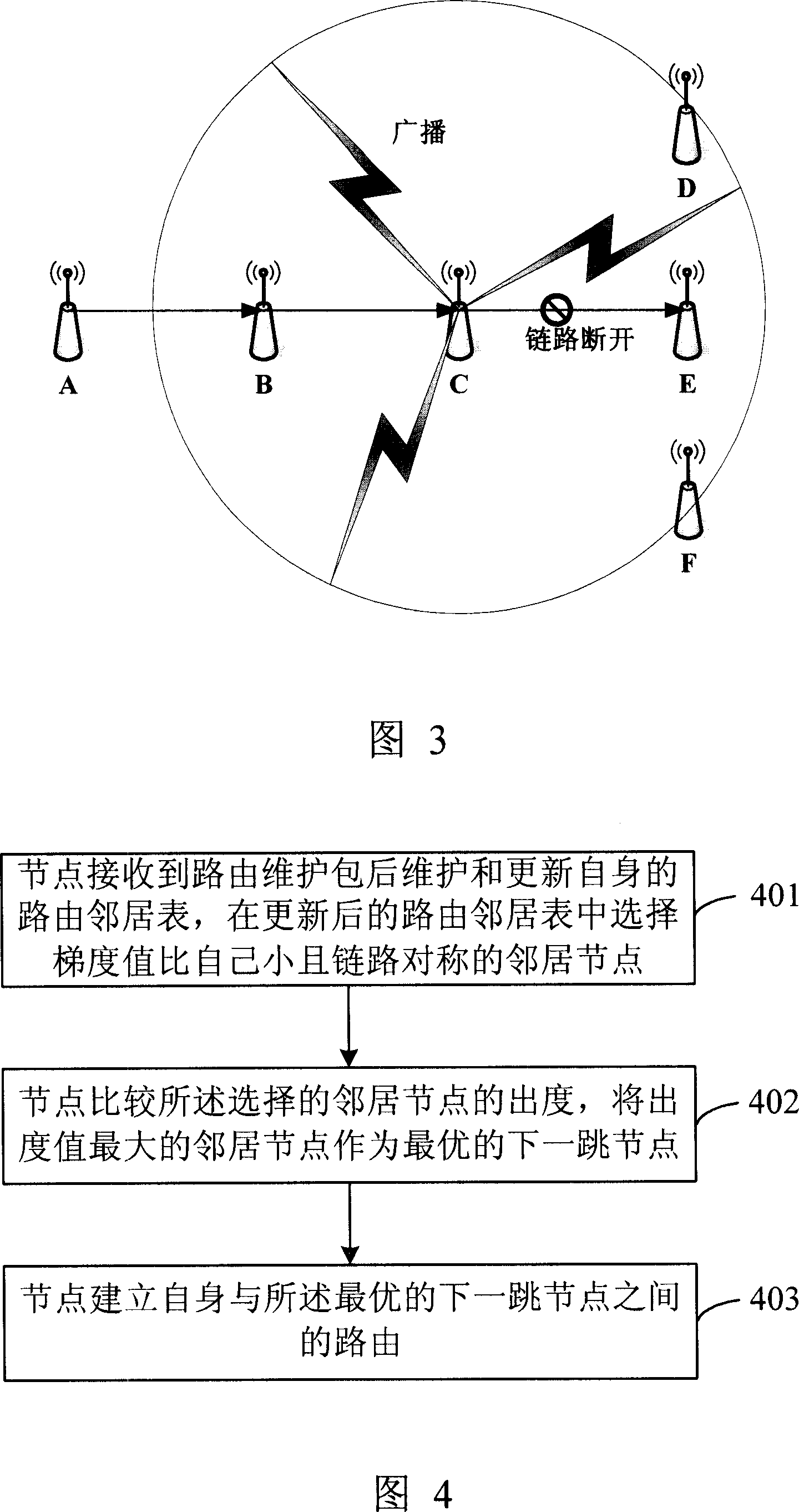
The method comprises: a) after receiving the routing maintenances packet, the node maintains and updates its own routing neighbor list, and selects the neighbor nodes whose gradient value are less than its own gradient value and which have link symmetry from the updated routing neighbor list; the node compares the out-going degrees of the selected neighbor nodes, and takes the neighbor node with maximal out-going degree as the optimal next jump node; c) the node establishes the route between itself and the optimal next jump node.

Description

technical field [0001] The invention relates to the technical fields of embedded systems and wireless sensor networks, in particular to a method for establishing a wireless sensor network route based on a routing neighbor table. Background technique [0002] Wireless sensor network (wireless sensor network) is a network system composed of a large number of cheap micro sensor nodes deployed in a certain area. These sensor nodes form a task-oriented self-organizing network system through wireless communication. The purpose is to cooperatively perceive, collect and process target information in the network coverage area, and control or send it to the observer. [0003] Wireless sensor networks are now seen as the next evolution in areas such as environmental monitoring, building monitoring, utilities, industrial control, home, ship and transportation system automation. The basic elements of a wireless sensor network are sensor nodes. General wireless sensor nodes use cheap lo...

Claims


Application Information

Patent Timeline
IPC IPC(8): H04L12/28H04L12/56H04L12/24H04L45/122
Inventor 蒋文丰夏鹏孙路徐勇军李晓维
Owner INST OF COMPUTING TECH CHINESE ACAD OF SCI
Learn More