Rare earth sintered magnet and process for producing the same

A technology of sintered magnets and manufacturing methods, applied in the direction of inductance/transformer/magnet manufacturing, permanent magnets, magnetic materials, etc., can solve the problem of small coercive force improvement effect, and achieve the effect of increasing coercive force and suppressing the reduction

Active Publication Date: 2007-07-25
HITACHI METALS LTD
View PDF3 Cites 53 Cited by
  • Summary
  • Abstract
  • Description
  • Claims
  • Application Information

AI Technical Summary

Problems solved by technology

Therefore, for magnets with a thickness of 3 mm or more, the effect of improving the coercive force is small

Method used


Image

  • Rare earth sintered magnet and process for producing the same
  • Rare earth sintered magnet and process for producing the same
  • Rare earth sintered magnet and process for producing the same

Examples


Embodiment 1

[0080] Using the strip casting method, from Nd 12.5 Fe 78.5 co 1 B 8 Composed alloy ingots are produced to produce alloy flakes with a thickness of 0.2 to 0.3 mm. Next, the flakes are filled in a container, hydrogen gas of 500 kPa is stored at room temperature, and then released to obtain an amorphous powder with a size of about 0.15 to 0.2 mm, which is then pulverized by a jet mill to produce a powder of about 3 μm. micro powder.

[0081] After adding and mixing 0.05% by mass of zinc stearate to the micropowder, it was press-molded in a magnetic field, packed into a vacuum furnace, and sintered at 1080° C. for 1 hour to obtain a cubic magnet block material of 10 mm square.

[0082] Next, this cubic magnet block material was cut with a grinding wheel to produce a Nd—Fe—B based rare earth magnet having a length of 10 mm, a width of 10 mm, and a thickness of 5 mm. The product in this state was used as it is as a comparative sample (1). Thickness is 5mm, volume is 500mm 3 ...

Embodiment 2

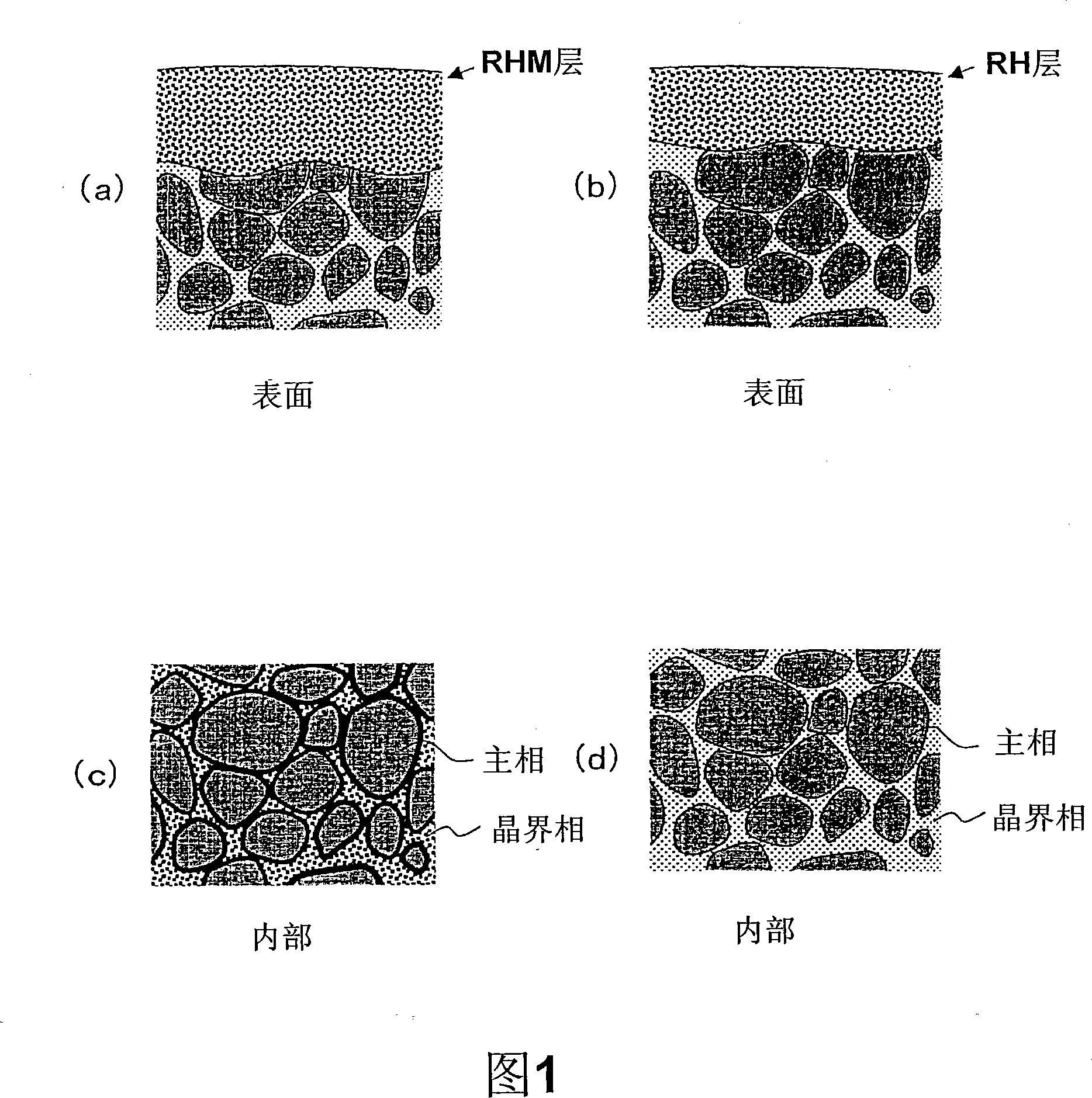
[0091] A Nd-Fe-B rare earth magnet with a length of 10 mm, a width of 10 mm, and a thickness of 4 mm was fabricated by cutting, and then formed on the surface of the Nd-Fe-B rare earth magnet using the vapor deposition device shown in Figure 3. RHM alloy film. A Tb-30% by mass Cu alloy (terbium-copper alloy) was used as the molten vapor-deposited product.

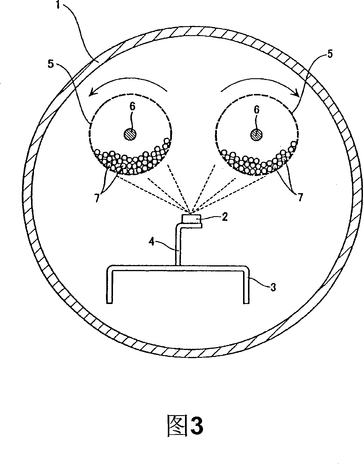
[0092] The actual film-forming operation by vapor deposition is performed in the following steps. After placing the three cut Nd-Fe-B rare earth magnets of a predetermined shape in the vacuum chamber of the vapor deposition device, heating and melting the TbCu alloy (terbium copper alloy) to evaporate it, and In the same manner as in Example 1, a 2 μm TbCu alloy (terbium copper alloy) film was formed on the surface of the Nd—Fe—B based rare earth magnet.

[0093] The magnetic properties of each sample were measured with a BH tracer after applying pulse magnetization of 3 MA / m. The demagnetization curves of Example 2 and ...

Embodiment 3

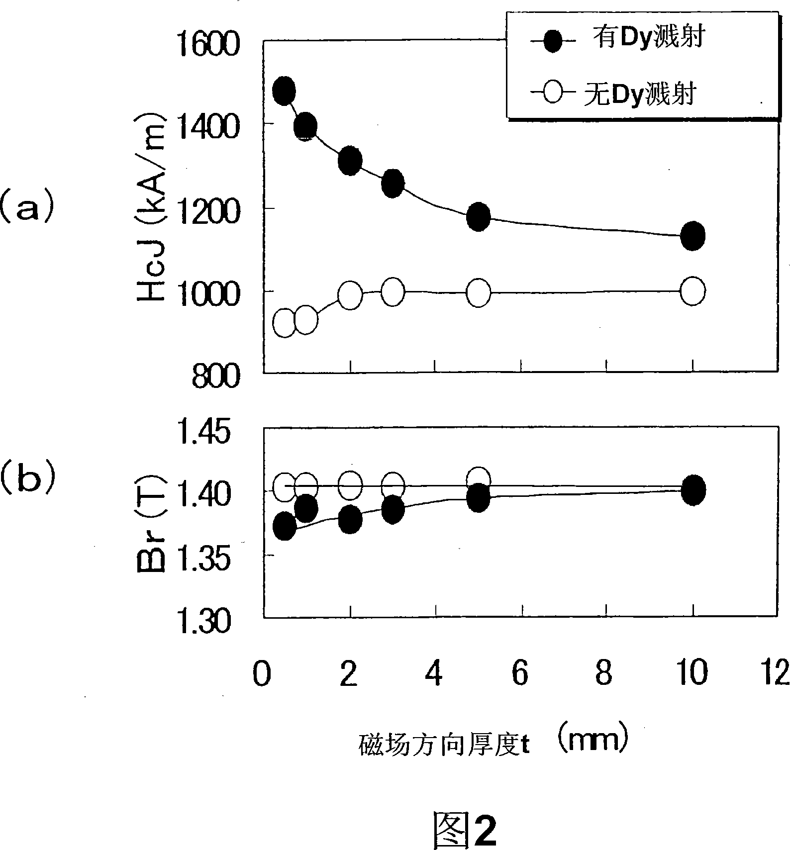
[0097] A Nd-Fe-B rare earth magnet with a length of 10 mm, a width of 10 mm, and a thickness of 6 mm was produced by cutting, and then, using the vapor deposition device shown in Figure 3, the Nd-Fe-B rare earth magnet was formed on the surface. RHM alloy layer. As the molten evaporated material, a Dy-20% by mass Fe alloy (dysprosium-iron alloy) was used.

[0098] The actual film-forming operation by vapor deposition is performed in the following steps. After placing the above-mentioned Nd-Fe-B rare earth magnets of three predetermined shapes in the vacuum chamber of the vapor deposition device, heating and melting the DyFe alloy (dysprosium-iron alloy) to evaporate it, in addition, In the same manner as in Example 1, a DyFe alloy (dysprosium-iron alloy) film of 2 μm was formed on the surface of the Nd—Fe—B based rare earth magnet.

[0099] The magnetic properties of each sample were measured with a BH tracer after applying pulse magnetization of 3 MA / m. The demagnetization...


PUM

PropertyMeasurementUnit
thicknessaaaaaaaaaa
thicknessaaaaaaaaaa
thicknessaaaaaaaaaa

Abstract

In the present inventive process for producing an R-Fe-B rare earth sintered magnet, first, there is prepared an R-Fe-B sintered magnet whose main phase consists of R2Fe14B compound crystal grains containing light rare earth element RL (at least one of Nd and Pr) as main rare earth element R. Subsequently, the sintered magnet body on its surface is coated with an RHM alloy layer composed of RH (wherein RH is one or two or more rare earth elements selected from among Dy, Ho and Tb) and metal M (wherein M is one or two or more metal elements selected from among Al, Cu, Co, Fe and Ag), the metal M forming RHM so as to induce a melting point lowering. Thereafter, heat treatment is carried out at 500 DEG to 1000 DEG C in vacuum or Ar atmosphere so as to cause the metal element M to diffuse from the surface into the internal portion of the sintered magnet and to cause the heavy rare earth element RH to diffuse from the surface into the internal portion of the rare earth sintered magnet body.

Description

technical field [0001] The present invention relates to having R 2 Fe 14 R-Fe-B series rare earth sintered magnet with B-type compound grains (R is a rare earth element) as the main phase and its manufacturing method, particularly involving light rare earth element RL (at least one of Nd and Pr) as the main phase The rare earth element R, and a part of the light rare earth element RL is replaced by the heavy rare earth element RH (at least one selected from Dy, Ho and Tb) R-Fe-B rare earth sintered magnet. Background technique [0002] Take Nd 2 Fe 14 R-Fe-B rare earth sintered magnets with B-type compounds as the main phase are known as the highest performance magnets among permanent magnets, and are used in voice coil motors (VCM) of hard disk drives and hybrid vehicles Various motors such as electric motors, and home appliances, etc. When R-Fe-B based rare earth sintered magnets are used in various devices such as motors, excellent heat resistance and high coercive f...

Claims


Application Information

Patent Timeline
Patent Type & Authority Applications(China)
IPC IPC(8): H01F41/02H01F7/02H01F1/08
CPCH01F41/20H01F41/24H01F41/18H01F1/0577H01F41/0293
Inventor 太田晶康森本英幸
Owner HITACHI METALS LTD
Why Eureka
Try Eureka