Brake system for motor vehicle

A brake system and motor vehicle technology, applied in the field of brake systems, can solve problems such as adverse consequences

Inactive Publication Date: 2007-08-01
陈增新
View PDF2 Cites 5 Cited by
  • Summary
  • Abstract
  • Description
  • Claims
  • Application Information

AI Technical Summary

Problems solved by technology

However, these improvements are often only used in emergency situations, and may cause many adverse consequences

Method used


Image

  • Brake system for motor vehicle
  • Brake system for motor vehicle
  • Brake system for motor vehicle

Examples


Embodiment 1

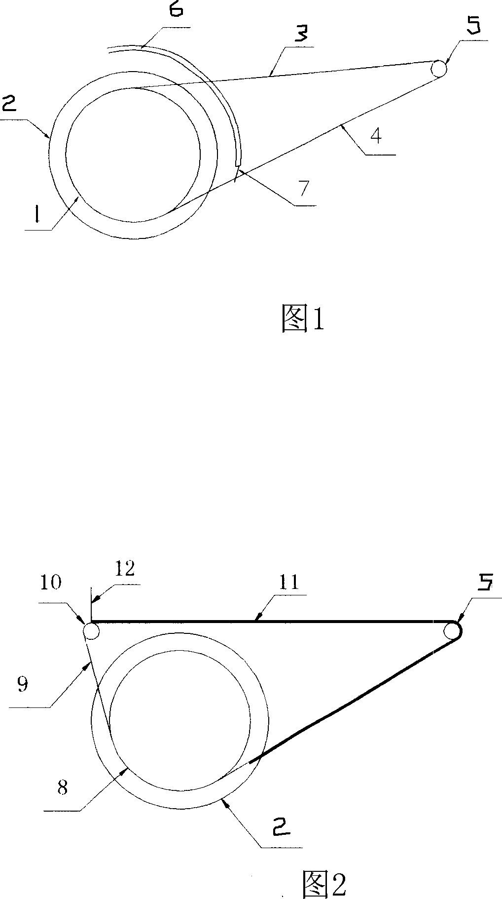
[0041] As shown in Figure 1, a gear 1 that can rotate with the wheel is arranged on both sides of the wheel 2, and its radius is slightly smaller than the radius of the wheel. The chain 3 on the gear 1 is interlocked with a gear fixed on the axle 5 on the vehicle frame at the rear of the wheel 2 . Movable hook is arranged on the chain 3, and when not braking, hook lies on the chain 3, and when braking, hook stretches out under the stirring of cross bar.

[0042] Friction plate box 6 is installed on the vehicle frame above wheel, and friction plate box is similar to magazine device, and spring is arranged in the interior, and friction plate can be pushed toward device outlet. The friction disc box afterbody is opened at the wheel rear, and railing 7 is established on it, the friction disc that can be unloaded from chain 4, and it is extruded into friction disc case 6.

[0043]The friction plate is shallow U-shaped, made of wear-resistant material, has a certain strength, and t...

Embodiment 2

[0047] As shown in FIG. 2 , two grooves 8 are provided on both sides of the wheel 2 in the radial and circumferential direction, and the radius of the grooves 8 is slightly smaller than the radius of the wheel 2 . There is a sliding bearing 10 on the top of the wheel, and the crawler belt 11 is covered. The two sides of the crawler belt 11 are steel cables 9, and the steel cables 9 are wound around the grooves 8 at the front and bottom of the wheel 2 and the linkage shaft fixed on the rear of the wheel 2 and the frame. 5 and the upper sliding bearing 10. Part steel cable 9 of crawler belt 11 front ends about half wheel circumference and crawler belt 11 can slide, but there is elastic rope to link steel cable 9 head and crawler belt 11 head. The crawler belt 11 rear portion is connected with the steel cable of corresponding position. There is a baffle plate 12 in the front of the sliding bearing 10, and when the vehicle was running normally, the baffle plate 12 stretched down,...

Embodiment 3

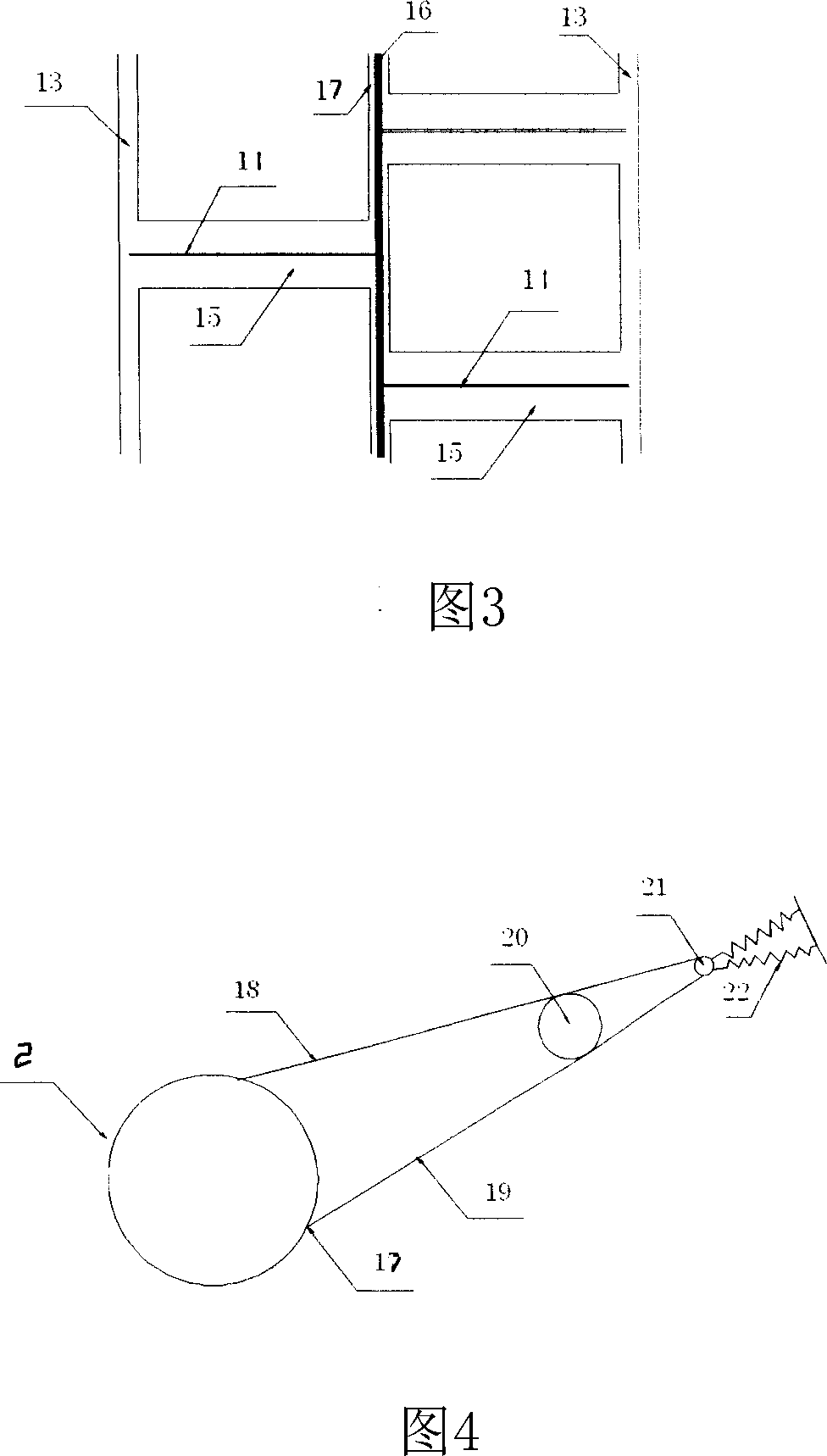
[0051] As shown in Fig. 3 and Fig. 4, a groove 17 is established in the radial middle part of the outer circumference of the wheel 2, and a flywheel 16 is arranged inside, and a chain 18 is formed on the flywheel 16. A groove 13 is arranged in the radial direction on both sides of the inner and outer sides. A plurality of dimples 15 are axially arranged on the outer peripheral surface of the wheel, and friction cables 14 are arranged in the dimples 15 . One end of the friction cable 14 is connected to the rotatable part on the flywheel 16, and the other end is connected to the grooves 13 on both sides of the wheel, and can slide in the grooves 13. Chain 18 is fixed on the one-way gear 20 on the axle on the vehicle frame through wheel 2 outer back top and rotates on slip ring 21. One group of other ends are fixed on the spring 22 on the vehicle frame on the slip ring.

[0052] As shown in FIG. 4 , when braking, under the rightward traction force of the spring 22 , the frictio...


PUM


Abstract

The vehicle braking system in the invention includes energy supply device, control device and wheels, it is characterized by: it also includes wear-resistant parts and linkage components. The wear-resistant parts attached on the wheels contact with ground when braking, the linkage components is linked with wear-resistant parts and with the axle which is fixed on the car frame together with wheel out parts, the energy supply device is ganged with the axle out the wheel under the control of control device, the braking force acts the wheels through the linkage components and the wear-resistant parts. The energy supply device may include electrometric element, and it transforms the kinetic energy into elastic potential energy when braking, then the elastic potential energy can be transformed into kinetic energy again when the brake is clapped. The invention is different from the previous design thinking, it can effectively improve the safety, fuel economic performance and manipulation performance of vehicles, is a significant innovation in the brake technology field. It can be used for motorcycles, cars, trains and other automobiles.

Description

technical field [0001] The invention relates to a brake system, in particular to a brake system for motor vehicles (including motorcycles, automobiles, trains, etc.). Background technique [0002] The braking systems of motor vehicles, such as motorcycles, automobiles, trains, etc., generally rely on friction to brake. The braking system prevents the wheel from rotating through the friction force between the brake pads and the wheel, and the wheel prevents the vehicle from moving through the friction force with the contact surface. [0003] Relying solely on the friction between the brake pads and the tires, the brakes are often powerless for vehicles with heavy weight and high speed. In order to solve this problem, manufacturers and relevant scientific research and technical personnel often consider two aspects. One is to increase the friction between the tire and the ground, such as designing and producing tires with a higher friction coefficient, winding iron chains on t...

Claims


Application Information

Patent Timeline
Patent Type & Authority Applications(China)
IPC IPC(8): B60T1/14B60T1/10B60K6/10
CPCF16D49/08B60T1/10
Inventor 陈增新
Owner 陈增新
Why Eureka
Try Eureka