Simple and convenient analog breaker circuit
A simple and convenient technology for simulating a circuit breaker, which is applied in the field of relay protection device testing with a microcomputer. It can solve the problems of inconvenient debugging and maintenance personnel, inconvenient portability, high price, etc., and achieves stable test performance, light weight and low cost. Effect
- Summary
- Abstract
- Description
- Claims
- Application Information
AI Technical Summary
Problems solved by technology
Method used
Image
Examples
Embodiment Construction
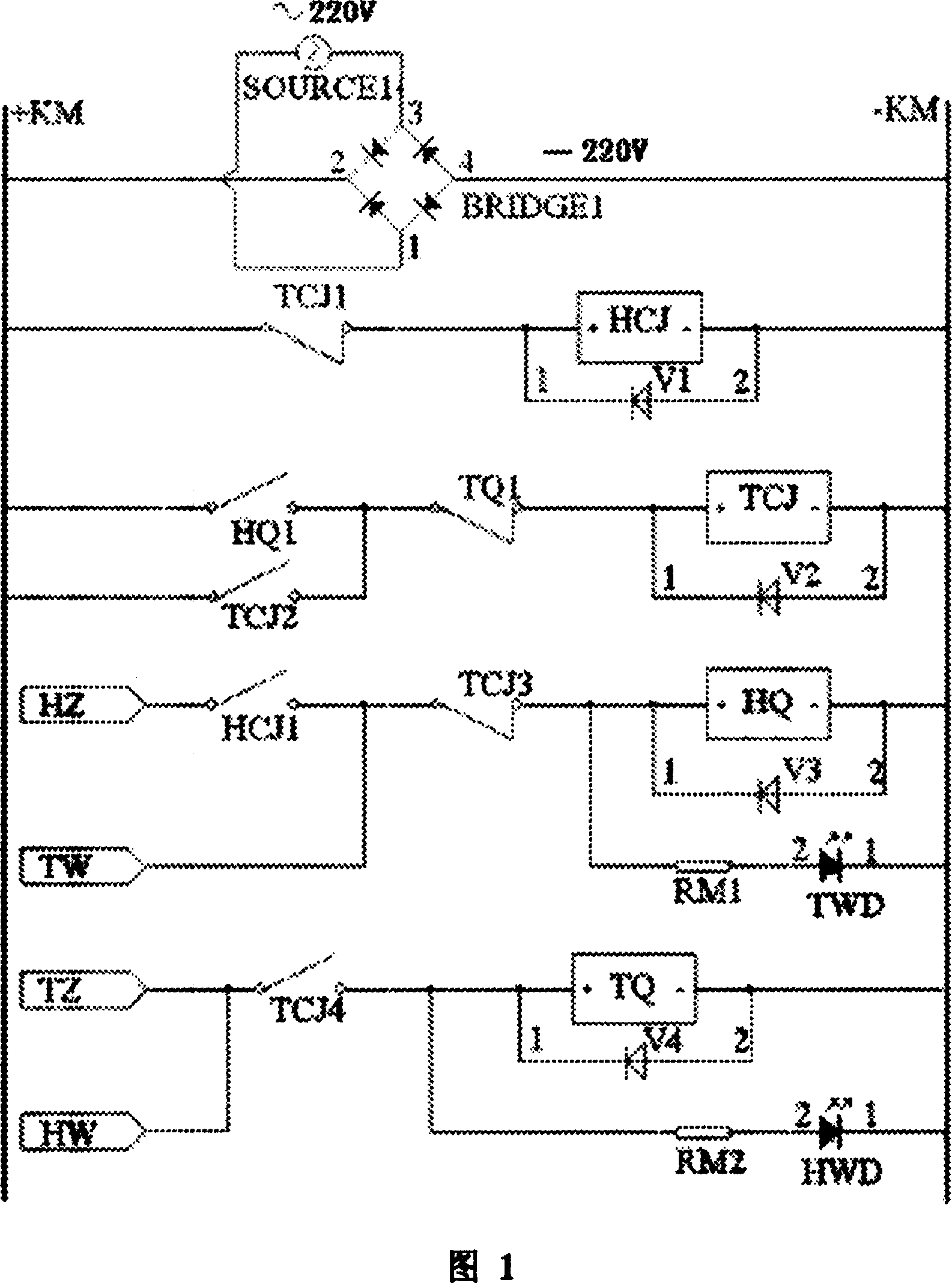
[0008] Referring to accompanying drawing 1, Fig. 1 is the circuit schematic diagram of the present invention, can find out from Fig. 1 that SOURCE1 is the 220V AC mains output source, BRIDGE1 is the rectifier bridge pile, +KM is the positive power supply bus bar of BRIDGE1 output DC, -KM is BRIDGE1 outputs the negative power supply bus of DC, and the DC 220V is between the bus +KM and the bus-KM. HCJ is the coil of the closing control relay, HCJ1 is the normally open contact of the closing control relay, TCJ is the coil of the trip control relay, TCJ1 and TCJ3 are the normally closed contacts of the trip control relay, TCJ2 and TCJ4 are the normally open contacts of the trip control relay Contacts, HQ is the coil of the closing relay, HQ1 is the normally open contact of the closing control relay, TQ is the coil of the closing relay, TQ1 is the normally closed contact of the closing control relay, V1, V2, V3, V4 are the coils Current discharge diode, TWD is the indicator light ...
PUM
 Abstract
Description
Claims
Application Information
 - R&D
- Intellectual Property
- Life Sciences
- Materials
- Tech Scout
- Unparalleled Data Quality
- Higher Quality Content
- 60% Fewer Hallucinations
Browse by: Latest US Patents, China's latest patents, Technical Efficacy Thesaurus, Application Domain, Technology Topic, Popular Technical Reports.
© 2025 PatSnap. All rights reserved.Legal|Privacy policy|Modern Slavery Act Transparency Statement|Sitemap|About US| Contact US: help@patsnap.com

