A portable UAV ejection mechanism

A kind of unmanned aerial vehicle and portable technology, which is applied in the direction of launching/dragging transmission devices, etc., can solve the problems of large volume and weight of the ejection rack, damage to the aircraft structure, and inability to be carried by manpower, etc., and achieve reduced structural strength requirements, simplified structure, and reduced cost Effect

Inactive Publication Date: 2015-11-25
SHENZHEN MINGXIN AVIATION TECH
View PDF4 Cites 7 Cited by
  • Summary
  • Abstract
  • Description
  • Claims
  • Application Information

AI Technical Summary

Problems solved by technology

When the aircraft is waiting to take off, if the elastic or pulling force of the catapult is directly transmitted to the aircraft, there are the following problems: 1. The structural strength requirements for the aircraft to withstand the elastic pulling force are high, which will increase the extra weight of the aircraft, which is very important for light and small UAVs. very unfavorable
Especially when it is necessary to wait for a fighter for a long time, it may cause structural damage to the aircraft
2. There must be a device on the ejection rack to lock the aircraft to prevent wrong ejection and take-off, which will also increase the complexity and weight of the ejection rack
If the pulling force of the bullet is not directly transmitted to the aircraft, it is necessary to make a special rack to install the aircraft, and then connect it with the elastic device. At present, most of the UAV ejection mechanisms do this, and its consequence is the size and weight of the ejection frame. They are too big to be carried by manpower

Method used


Image

  • A portable UAV ejection mechanism
  • A portable UAV ejection mechanism
  • A portable UAV ejection mechanism

Examples


Embodiment Construction

[0024] The present invention will be further described below in conjunction with the accompanying drawings and embodiments.

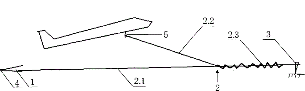
[0025] see figure 1 , the present invention provides a portable UAV ejection mechanism, which includes: an ejection frame 1, an ejection rope 2 and ground stakes 3. The aircraft is placed on the ejection rack 1. Described ejection rope 2 is made up of three ropes: the load-bearing rope 2.1 of waiting to fly at the tail, the elastic tension rope 2.3 of the flying tension rope 2.2 of the middle part and the front part. Waiting to fly bearing rope 2.1 and flying tension rope 2.2 are inelastic ropes, and its front end is knotted in elastic tension rope 2.3 rear end together, has been divided into three ropes of bifurcation from node. Waiting to fly the rear end of force rope 2.1 to be hung on the flying device 4 of ejection frame 1; The elastic pull rope 2.3 of ejection rope 2 can be stretched to 15m.

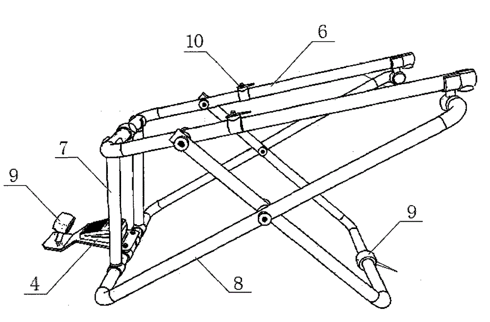
[0026] see figure 2 , is a schematic structural ...


PUM


Abstract

The invention provides a portable ejection mechanism for an unmanned aerial vehicle. The portable ejection mechanism comprises an ejection frame, an ejection rope and a ground pile. An airplane is arranged on the ejection frame. The ejection rope consists of three ropes, namely a force-bearing rope for flying at a tail part, a flying tension rope in a middle part and an elastic tension rope at a front part. The force-bearing rope for flying and the flying tension rope are respectively an elasticity-free rope, and the front end of the force-bearing rope for flying and the front end of the flying tension rope are tied together at the back end of the elastic tension rope, and are divided into three forked ropes from a knot. The back end of the force-bearing rope for flying is suspended on the flying device of the ejection frame; the back end of the flying tension rope is suspended on an ejection pothook arranged at the bottom of the airplane; and the front end of the elastic tension rope is suspended on the ground pile. Due to the use of the portable ejection mechanism for the unmanned aerial vehicle provided by the invention, the structure of the ejection support can be greatly simplified, and the weight of the ejection support can be reduced. The unmanned aerial vehicle can be under the status to be emitted for a long time, and the unmanned aerial vehicle can immediately emit once a fighter is captured. When the unmanned aerial vehicle is emitted, the ejection rope can be stretched, the enough emitted energy can be stored, and the airplane can not directly bear the tension force of the ejection rope.

Description

technical field [0001] The invention relates to a portable unmanned aerial vehicle ejection mechanism, which is suitable for various small unmanned aerial vehicles. Background technique [0002] At present, the UAV ejection mechanism must keep the ejection force generating device in an energy storage state before the aircraft ejection, such as stretching the launching elastic cord or compressing or stretching the launching spring. When the aircraft is waiting to take off, if the elastic or pulling force of the catapult is directly transmitted to the aircraft, there are the following problems: 1. The structural strength requirements for the aircraft to withstand the elastic pulling force are high, which will increase the extra weight of the aircraft, which is very important for light and small UAVs. Very unfavorable. Especially when it is necessary to wait for a fighter plane for a long time, structural damage may occur to the aircraft. 2. There must be a device on the ejec...

Claims


Application Information

Patent Timeline
Patent Type & Authority Patents(China)
IPC IPC(8): B64F1/06
Inventor 郝南楠
Owner SHENZHEN MINGXIN AVIATION TECH
Why Eureka
Try Eureka