Decoding and display method for video code stream

A decoding and code stream technology, applied in the field of decoding and display that can reduce the size of memory usage, can solve the problems of inability to achieve signal-to-noise ratio, compression ratio limitation, and image quality degradation, and achieve the effect of saving memory usage

Inactive Publication Date: 2007-08-01
ALICORP
View PDF0 Cites 4 Cited by
  • Summary
  • Abstract
  • Description
  • Claims
  • Application Information

AI Technical Summary

Problems solved by technology

However, these compressions cannot achieve a good signal-to-noise ratio (S/N ratlo) in the face of some more complex tes

Method used


Image

  • Decoding and display method for video code stream
  • Decoding and display method for video code stream
  • Decoding and display method for video code stream

Examples


Example Embodiment

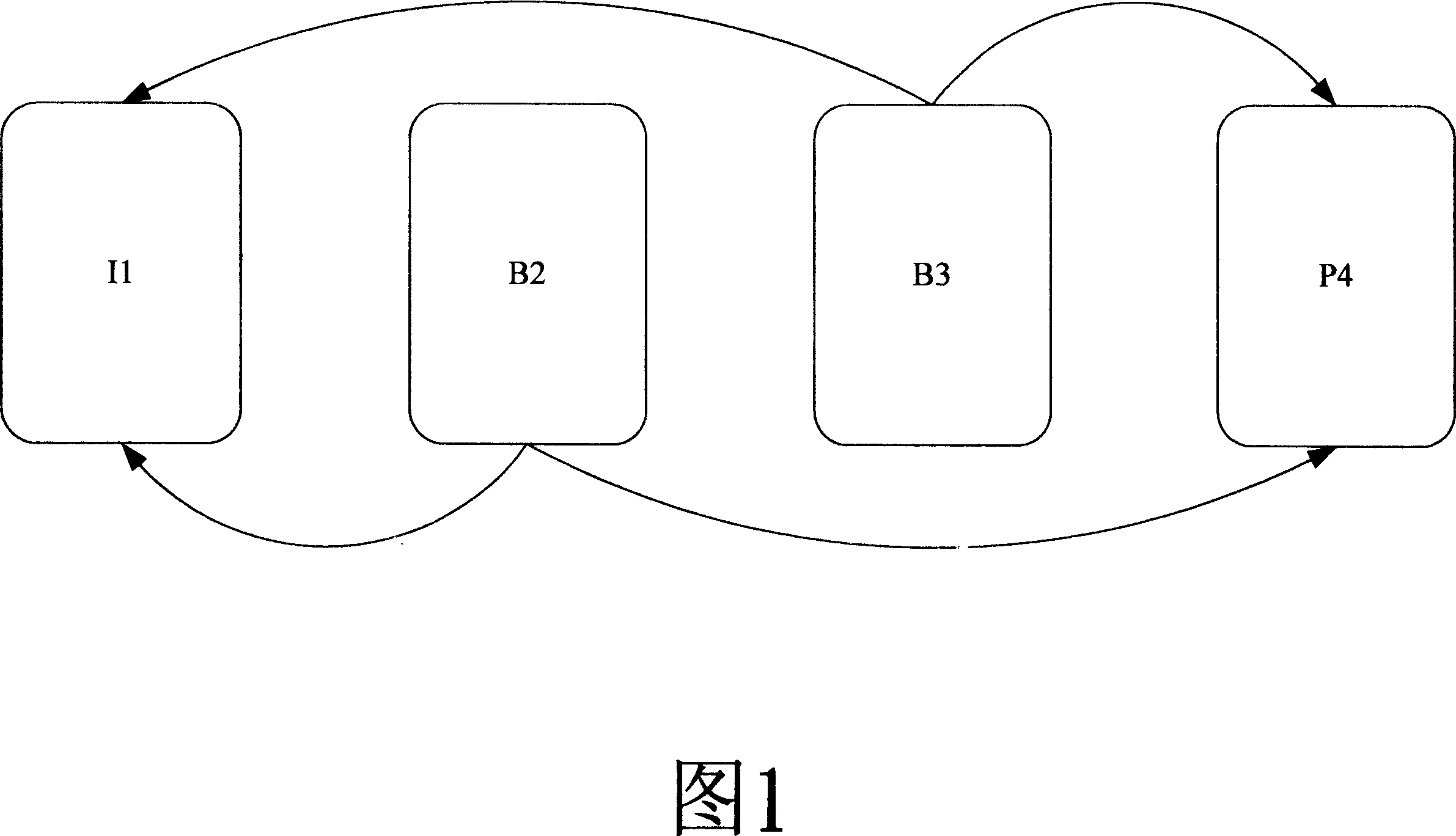
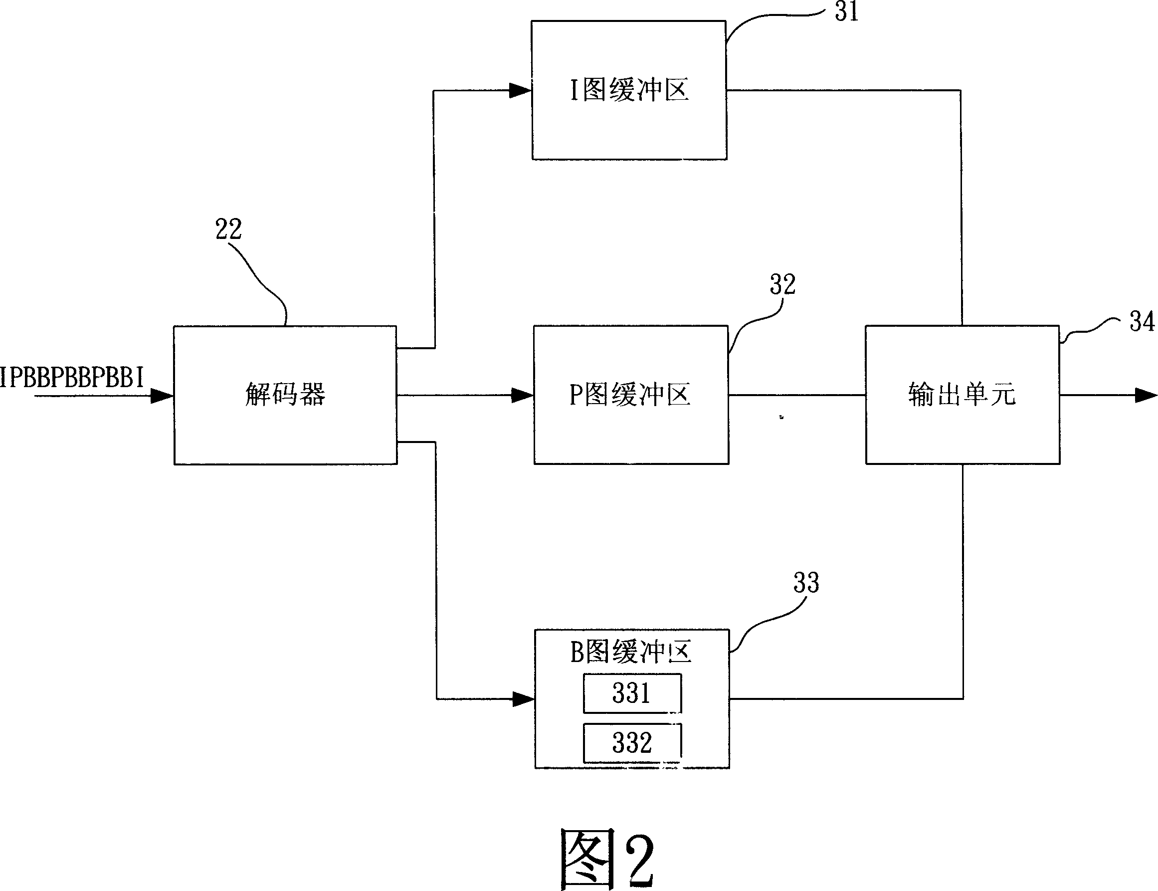
[0025] FIG. 2 is a functional block diagram of a display device 20 implementing the method of the present invention. For example, the image data in the data stream (bitstream) is input to the decoder 22 in the order of IPBBBPBBPBBI, where I denotes an Intra frame, P denotes a Predictive frame, B represents a bi-directionally predictive coding (Bi-directionally Predictive) frame. The decoder 22 determines whether the frame belongs to the I frame, the P frame or the B frame according to the flags of the frames in the code stream, and if it is an I frame, it is decoded and stored in the I frame buffer. 31; If it is a P picture frame, then decode and store in the P picture cache 32 according to the data of the I picture frame; If it is a B picture frame, then according to the data of the I picture frame and the P picture frame, the B picture frame is decoded and stored. Stored in the B picture buffer 33 . Then, the output unit 24 reads the I frame, the P frame, and the B frame i...


PUM


Abstract

The video flow comprises a plurality of inner coding frames, predictive coding frames, and bidirectional predictive coding frames every contained a first picture frame with multiple macro block units and a second picture frame. The disclosed decoding and displaying method comprises: (1) decoding the said first picture frame to store in a first buffer; (2) reading in the buffered frame to display; (3) decoding the said macro block unit to store in a second buffer less than the first one; (4) reading in and displaying the buffered block unit; (5) repeating (3) and (4) till decoding all block units.

Description

【Technical field】 [0001] The present invention relates to a decoding and displaying method, in particular to a decoding and displaying method capable of reducing memory usage. 【Background technique】 [0002] With the popularity of MPEG-based decoders such as DVD and STB, it is increasingly required to reduce the production cost of the whole machine. Nowadays, in addition to the cost reduction of the decoding chip itself, there are also new requirements for the size of the external storage unit. Therefore, how to realize image decoding and display with fewer storage units has become a trend. [0003] Most of the existing technologies aim at compressing the image itself, and transform the spatial data such as ADPCM, PCM, Hadamard, etc., so as to achieve the purpose of compression. For most common image sources, when the compression ratio is not very high, the loss of image quality can be said to be small, and the naked eye will basically not feel it. However, these compress...

Claims


Application Information

Patent Timeline
IPC IPC(8): H04N7/32H04N19/44H04N19/577
Inventor 王津福陈岳勇
Owner ALICORP
Why Eureka
Try Eureka