Foundation structure of steel tower

A foundation and iron tower technology, applied in the field of iron tower foundation structure, can solve the problems of more time and labor required for construction, more concrete pouring, and larger labor load, etc., to achieve labor costs, scale reduction, and excavation reduction Effect

Inactive Publication Date: 2007-08-01
THE TOKYO ELECTRIC POWER CO INC
View PDF3 Cites 4 Cited by
  • Summary
  • Abstract
  • Description
  • Claims
  • Application Information

AI Technical Summary

Problems solved by technology

[0009] In addition, when the bedrock is near the ground surface and it is difficult to excavate with heavy machinery, it is necessary to use blasting together, or it is necessary to assemble the soil retaining bracket mainly by manpower, which will increase the labor load and prolong the construction period. question
[0010] On the other hand, in the foundation (footing) supporting the foot of the iron tower, as shown in FIG. A cone-shaped shear crack 54 centered at the base of the
And, as shown in FIG. 27, when the pile body 55 is too close to the outer edge of the footing 53, shear cracks 56, 56... in the form of split cracks are generated from the fixed part to the outside, and the fixed part is destroyed.
In addition, when the footing is too thin, as shown in the figure, there will be problems such as a cone-shaped shear crack 54 centered on the pile body 55.
[0011] Therefore, if the footing 53 is designed to have sufficient resistance to these press-fit force, pull-out force, bending moment, and horizontal force without causing cracks, the scale of the footing becomes large, and also increases with the scale of the footing. Correspondingly, there are problems such as increased excavation volume and concrete pouring volume, and construction requires a lot of time and labor

Method used


Image

  • Foundation structure of steel tower
  • Foundation structure of steel tower
  • Foundation structure of steel tower

Examples


no. 1 example

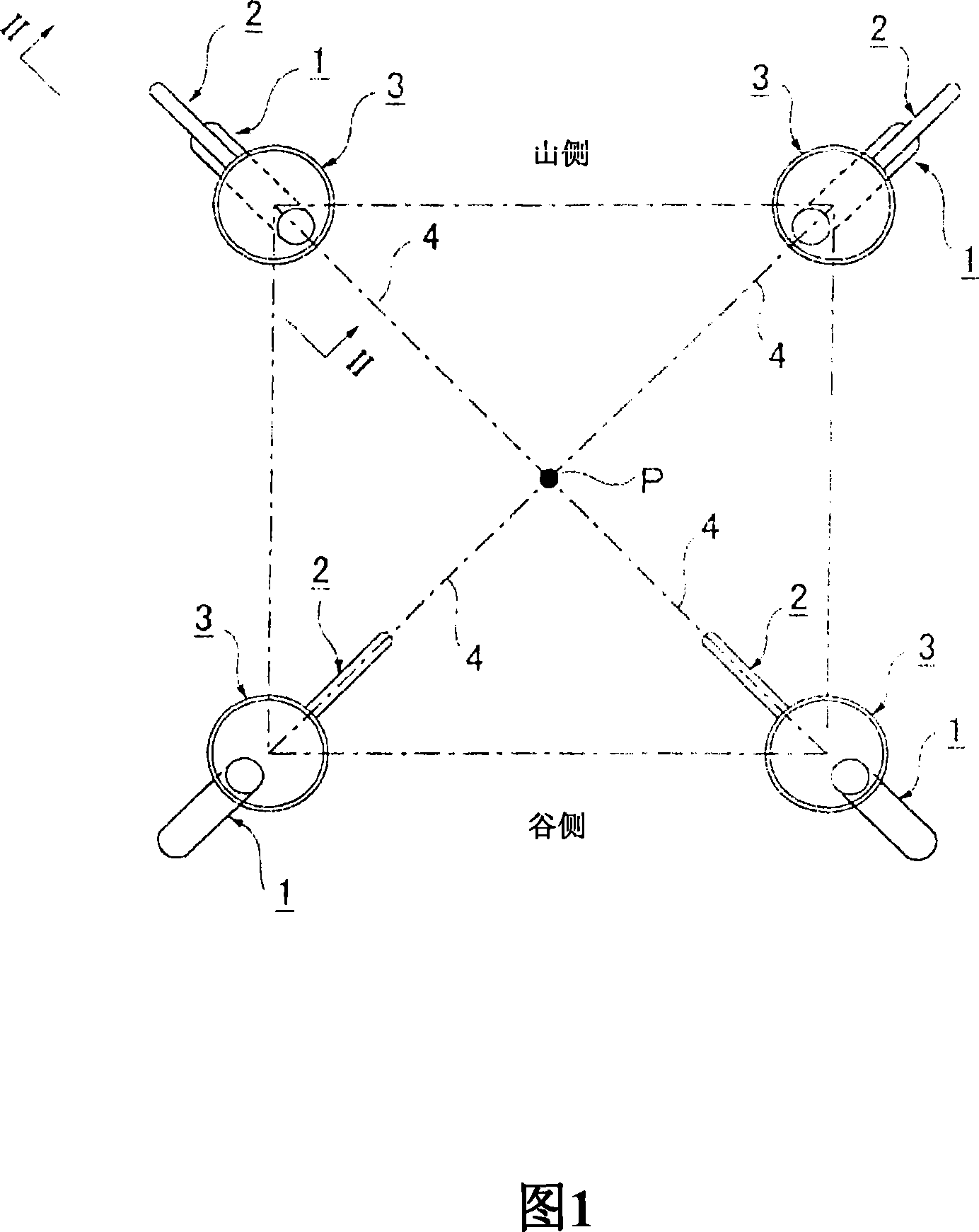
[0077] As shown in Figures 1 and 2, the iron tower foundation structure of the present invention includes: one or more main piles 1 arranged in the foundation along a direction roughly consistent with the direction S of the above-mentioned main pile 4; The plane direction of the foundation and the tower center P is set in one or more auxiliary piles 2 in the foundation; and the combination structure 3 combining the above-mentioned main pile 1 and the auxiliary pile 2 and fixing the base of the above-mentioned main pile 4 .

[0078] Described in more detail below.

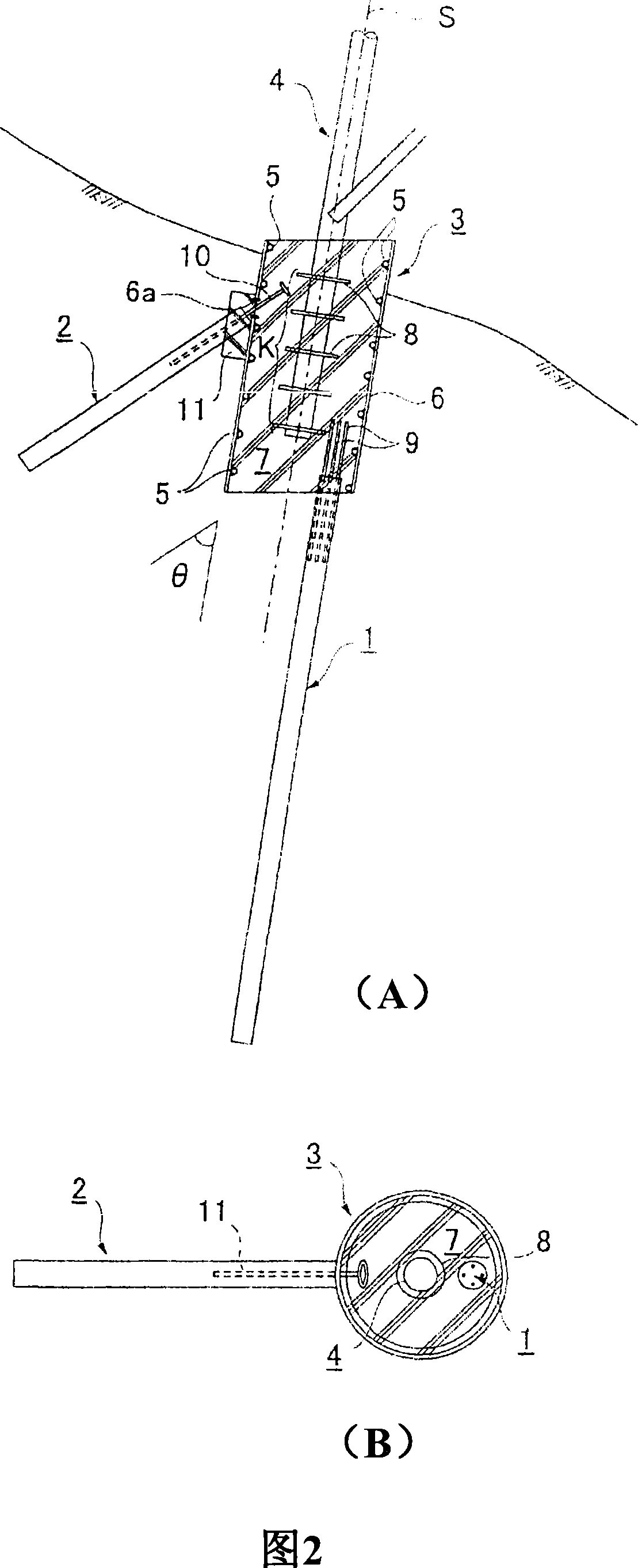
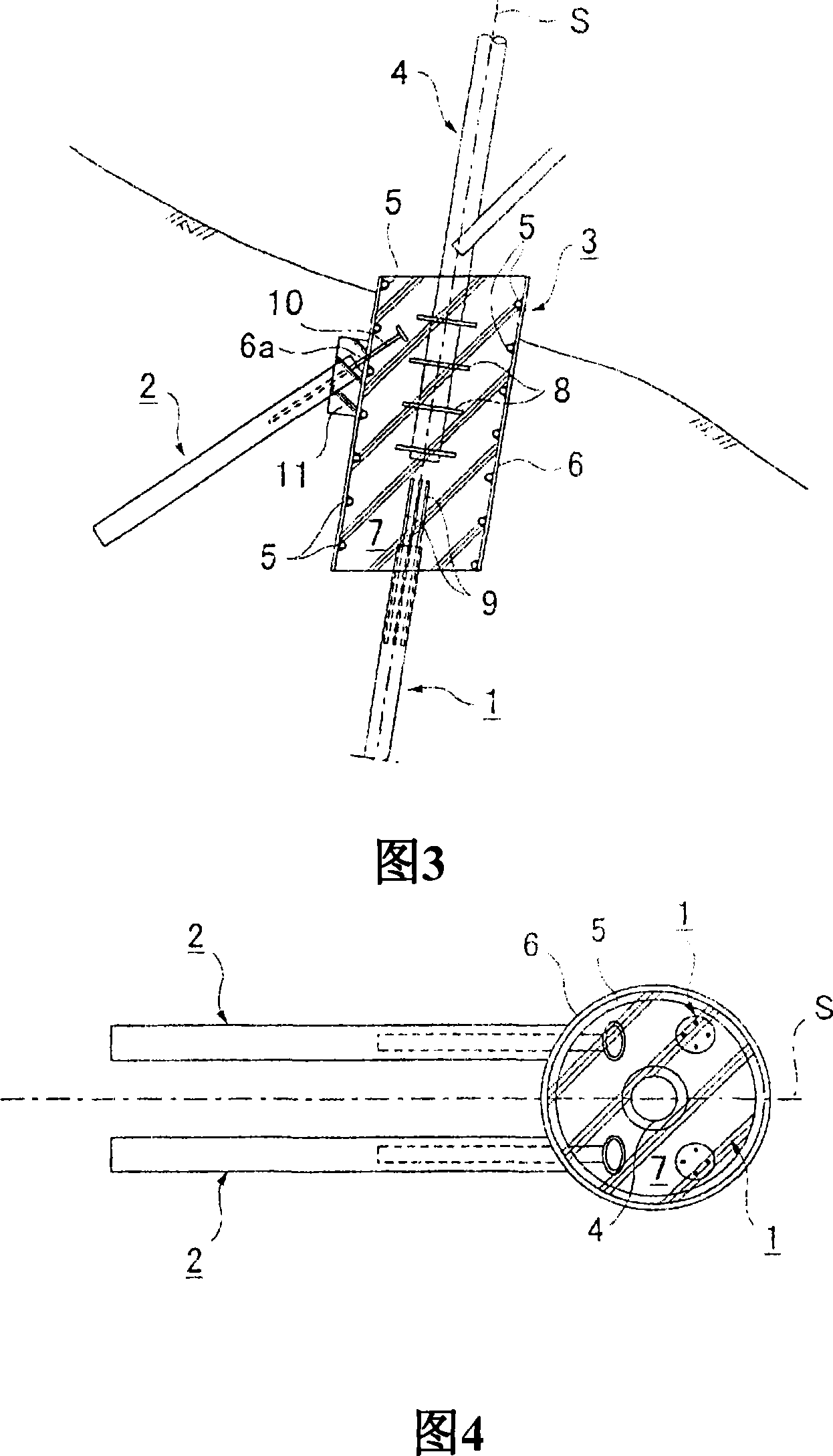
[0079] As the concrete structure 3, a structure composed of thick-walled steel pipe 6 with a diameter of about 1000 to 5000 mm and a thickness of about 20 to 30 mm and concrete 7 poured into the steel pipe 6 is preferably used.

[0080] On the inner wall surface of the above-mentioned steel pipe 6, the shear flanges 5, 5... fixedly arranged along the circumferential direction are arranged in multiple stages along th...

Embodiment

[0096] Next, various tests were conducted in order to verify the effect of the combined pile group of the present invention and the dynamics of piles when a load acts.

[0097] (1) Displacement characteristics of combined pile groups

[0098] In the actual site, as shown in Fig. 9, the beam 20 is fixed by the reaction piles 21 and 21, the foundation composed of the main pile 1 and the auxiliary pile 2 is pulled out by the jack 22, and the displacement in the X-Y direction is investigated. As a result, as shown in FIG. 10 , while displacement occurs in the vertical direction, the auxiliary pile 2 is displaced in a substantially vertical direction.

[0099] (2) Displacement

[0100] In the same field test, as shown in Figure 11, the displacement in the load direction is taken as the horizontal axis, and the displacements in each case of the single pile and the combined pile group are compared. As a result, it became clear that the combined pile group can suppress displacement ...


PUM


Abstract

To provide a foundation structure of a tower capable of reducing labor load, construction cost, and production steps by reducing the scale of the structure of a foundation and facilitating construction. This foundation structure of the tower for supporting the main pedestals (4) of the tower comprises main piles (1) installed in the ground along directions roughly matching the directions of the main pedestals (4), auxiliary piles (2) installed in the ground along surface directions connecting the foundations to the center of the tower in plan view, and joining structures (3) joining the main piles (1) to the auxiliary piles (2) and to which the base parts of the main pedestals (4) are fixed. The joining structures (3) are built, for example, by placing a concrete (7) in a steel pipe (6). The top parts of the main piles (1) are joined to the lower surfaces of the joining structures (3), and the top parts of the auxiliary piles (2) are joined to the side faces thereof.

Description

technical field [0001] The present invention relates to a foundation structure of an iron tower for supporting main piles of the iron tower. Background technique [0002] Especially as the foundation structure of a power supply tower in a mountainous area, when the supporting layer is shallow, an inverted T-shaped foundation 50 as shown in FIG. Mainly adopt the deep foundation 51 as shown in FIG. 25 . [0003] On the other hand, the foundation of the above-mentioned power supply tower is more strongly affected by the pay-out tension of the wire and wind load such as typhoon or monsoon than the influence of the tower's own weight or the wire's own weight. As a result, the overturning moment becomes large compared to all the compressive loads due to other factors, so that a compressive load acts on the tower foot on the leeward side, and approximately equal to the compressive load acts on the tower foot on the windward side. 70% of the pull-out load (pull-out force) of the l...

Claims


Application Information

Patent Timeline
Patent Type & Authority Applications(China)
IPC IPC(8): E02D27/42E02D27/12
CPCE02D27/42E02D27/12
Inventor 田边成松尾敏内藤幸弘
Owner THE TOKYO ELECTRIC POWER CO INC
Why Eureka
Try Eureka