
Punch forming machine for double-hook on antiskid chain
A technology of forming machine and stamping mechanism, applied in belt/chain/gear, mechanical equipment, gear transmission, etc., can solve the problems of poor safety, low efficiency, high labor intensity of workers, etc., and achieve the effect of high work efficiency
- Summary
- Abstract
- Description
- Claims
- Application Information
AI Technical Summary
Problems solved by technology
Method used
Image

Examples
Embodiment 1
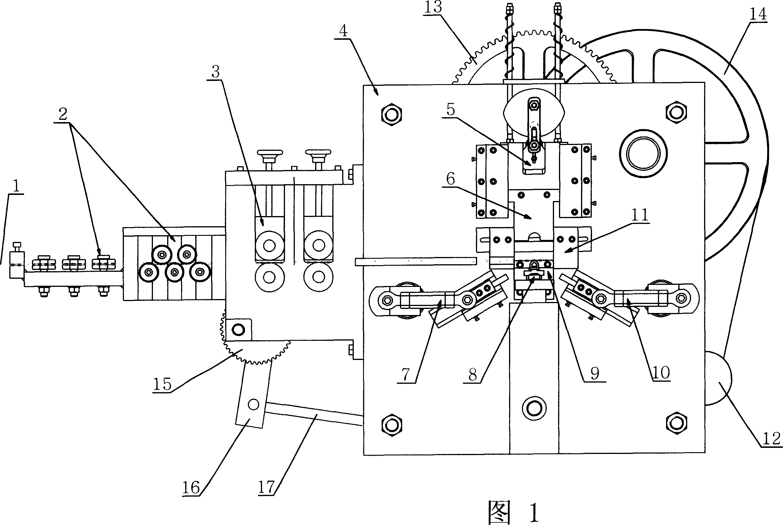
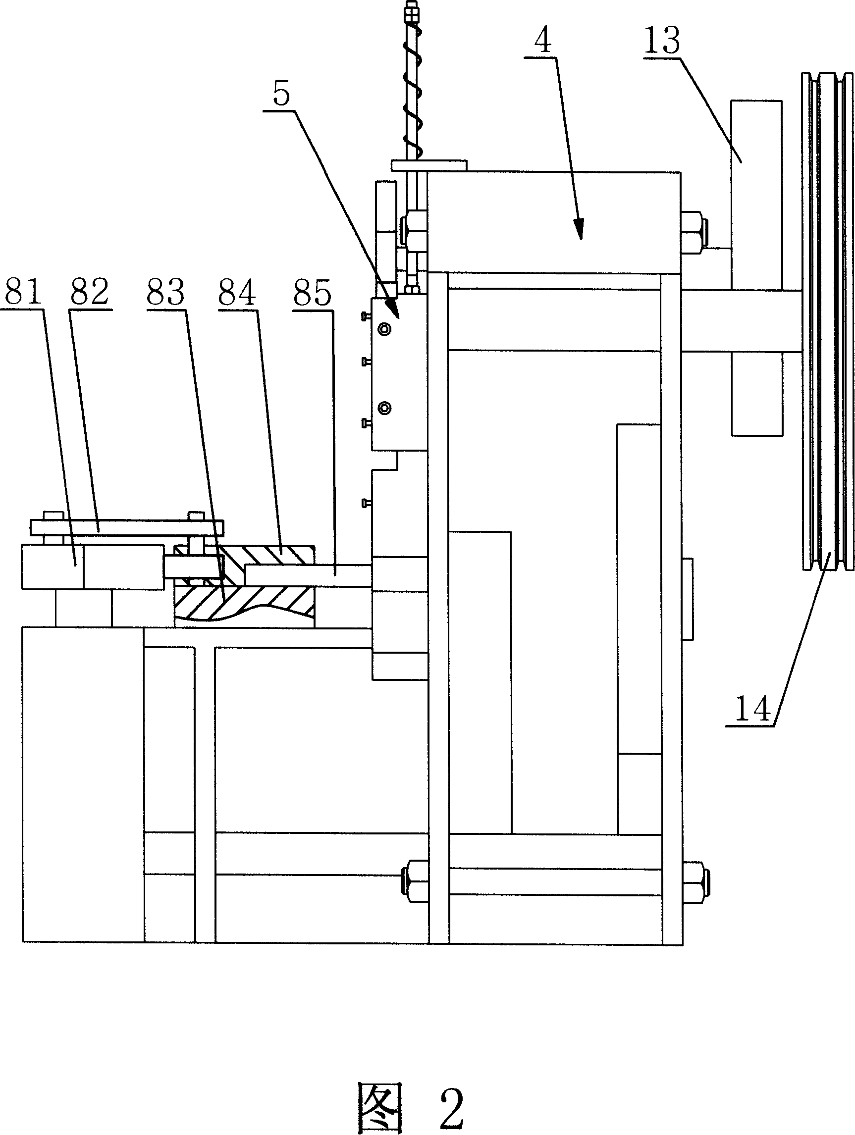
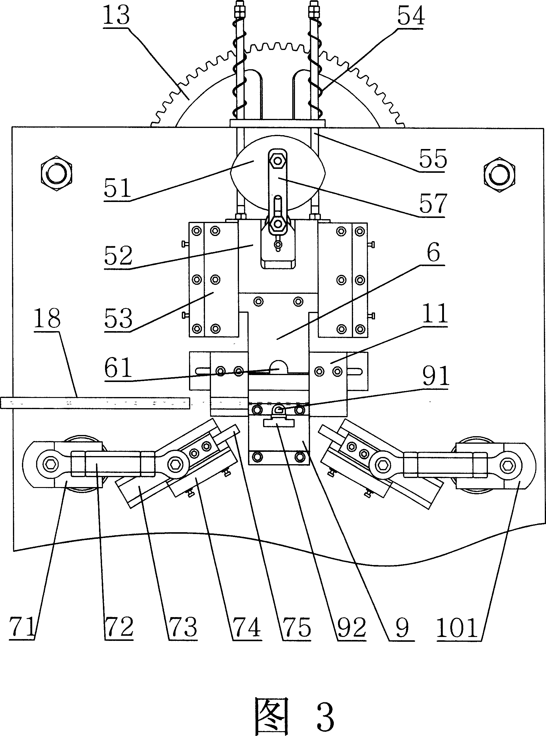
[0026] A stamping and forming machine with double hooks on an anti-skid chain as shown in Figures 1 and 2, includes a frame 4, and the feed end of the frame 4 is provided with a wire straightening mechanism 2 and an intermittent feeding mechanism 3, and the frame 4 is provided with the positioning frame 11 of positioning wire rod and mould, and the first action mechanism 5 that is punched vertically from top to bottom is arranged on the top of the positioning frame 11, and the bottom of the positioning frame 11 two sides is provided with the first action mechanism 5 that is stamped from both sides to the middle. Two action mechanisms, the front of the positioning frame 11 is provided with a third action mechanism 8 that is punched horizontally from front to back, wherein the second action mechanism is composed of a left stamping mechanism 7 and a right stamping mechanism 10 with the same structure and symmetrical arrangement ; The first action mechanism 5 and the second action ...
PUM
 Abstract
Description
Claims
Application Information