Method of driving microchannel fluid utilizing magnetic droplet

A fluid-driven, magnetic droplet technology, applied in magnetic liquids, microstructure devices composed of deformable elements, microstructure technology, etc. The effect of extensive cost, high reliability, and simple control logic

Inactive Publication Date: 2007-08-08
TSINGHUA UNIV
View PDF0 Cites 13 Cited by
  • Summary
  • Abstract
  • Description
  • Claims
  • Application Information

AI Technical Summary

Problems solved by technology

Currently commonly used integrated drive devices require moving parts, the processing a

Method used


Image

  • Method of driving microchannel fluid utilizing magnetic droplet

Examples


Embodiment Construction

[0010] The invention proposes a fluid driving method for a magnetic droplet microchannel. The specific implementation process of the present invention will be further described below in conjunction with the accompanying drawings.

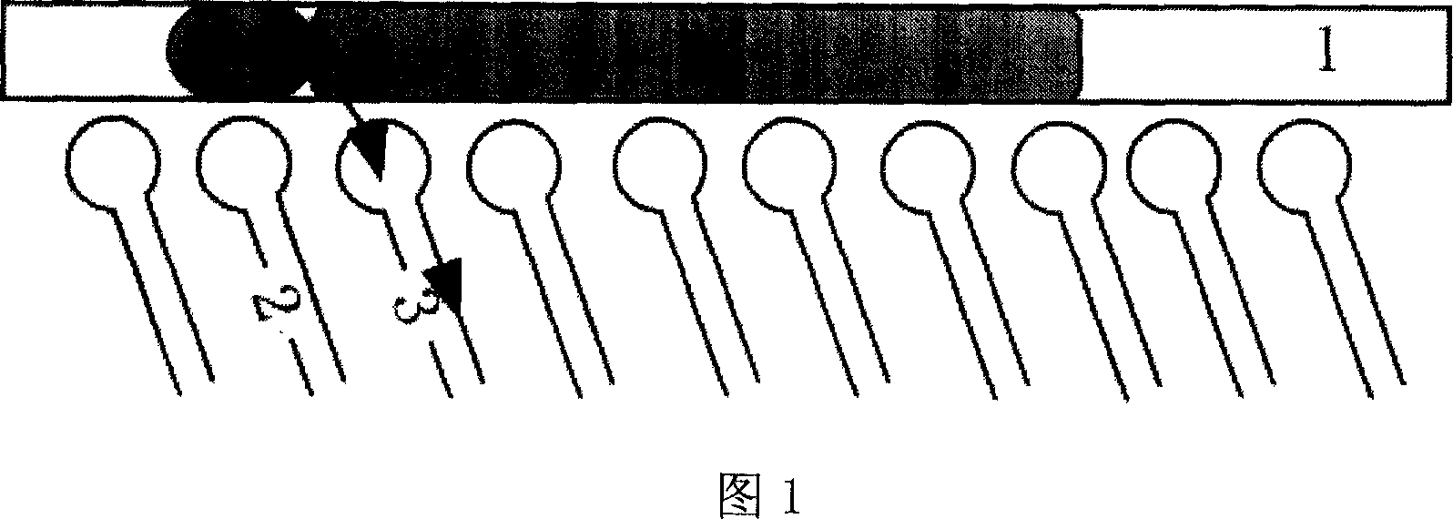
[0011] The invention is based on the principle that magnetic fluids are attracted by a magnetic field. As shown in Fig. 1 is a schematic diagram of the fluidic driving method of the magnetic droplet microchannel. A magnetic fluid droplet 4 and a driven fluid liquid column 5 are placed in the microchannel 1 on the substrate, and a series of microcurrent cells are arranged at the bottom or side of the channel along the direction of the channel, and 2 and 3 are any two microcurrent cells among many microcurrent cells. current element. If the driven fluid is expected to move from left to right, and the magnetic fluid droplet is just above the microcurrent cell 2, then the microcurrent cell 3 on the right side of the microcurrent cell 2 is energized, a...


PUM


Abstract

The invention relates to a fluid driving method inside a micro channel, which sets magnetic fluid drop and driven fluid post inside the micro channel, with several micro current elements along the channel direction. It is driven by electromagnetic principle, free from mechanic movement component, with high reliability, easy for micro machining, with reduced cost, controlled logic simplicity, relatively wide selection scope with low cost of the basic fluid of the magnetic fluid, selecting proper magnetic fluid to drive various fluids.

Description

technical field [0001] The invention belongs to the technical field of magnetic fluid, microelectromechanical system and biochip. In particular, based on the magnetic properties of the magnetic fluid, the liquid droplets of the magnetic fluid are used to drive the flow of other immiscible fluids. This method is driven by the principle of electromagnetic field force, has no mechanical moving parts, and is easy to implement using micromachining technology. , is a microchannel fluid actuation method using magnetic droplets. Background technique [0002] Micro-electro-mechanical systems and biochips are current research hotspots, in which fluid flow in micro-electro-mechanical systems plays an important role in the realization of certain system functions, but there is still a lack of devices that can be easily integrated into micro-electro-mechanical systems. Fluidic actuation methods within the system. Currently commonly used integrated drive devices require moving parts, the...

Claims


Application Information

Patent Timeline
IPC IPC(8): B81B3/00H01F1/44
Inventor 杨昆仑任建勋宋耀祖
Owner TSINGHUA UNIV
Why Eureka
Try Eureka