Sea wave electricity generating device

An ocean wave power generation and generator technology, which is applied to ocean energy power generation, engine components, machines/engines, etc., can solve the problems of complex structure, high cost, poor stability in use, etc., and achieve the effect of not easy to damage and long service life.

Inactive Publication Date: 2007-08-08
张新金
View PDF1 Cites 4 Cited by
  • Summary
  • Abstract
  • Description
  • Claims
  • Application Information

AI Technical Summary

Problems solved by technology

Due to the messy distribution of sliding ropes, the structure of the device is complicated and the cost is high

Method used


Image

  • Sea wave electricity generating device
  • Sea wave electricity generating device
  • Sea wave electricity generating device

Examples


Embodiment 1

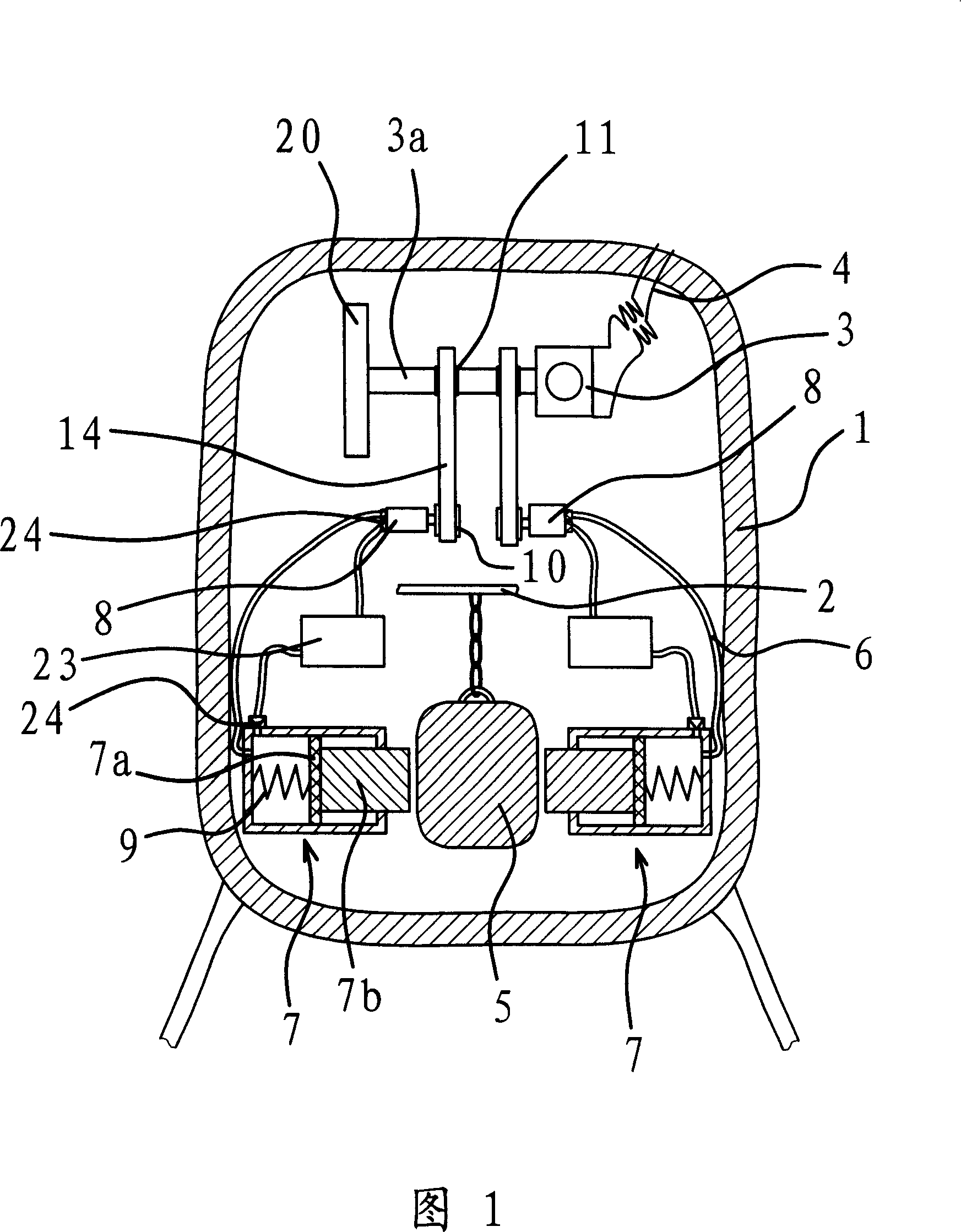
[0038] As shown in Figure 1, the wave power generation device is placed on the sea surface, and it includes a closed buoy 1 with a cavity inside, and the buoy 1 is connected to an anchor placed on the seabed through a rope.

[0039] The buoy 1 is provided with a bracket 2, a generator 3, a swing block 5, a hydraulic cylinder 7 and a hydraulic motor 8. The swing block 5 is hung on the support 2 by ropes, and the generator 3 has a rotating shaft 3a. The hydraulic cylinder 7 and the hydraulic motor 8 communicate through the pipeline 6, and a linkage mechanism is provided between the hydraulic cylinder 7 and the swing block 5, and a transmission mechanism is provided between the hydraulic motor 8 and the rotating shaft 3a of the generator 3, and the transmission mechanism The rotating shaft 3a can be continuously rotated in one direction.

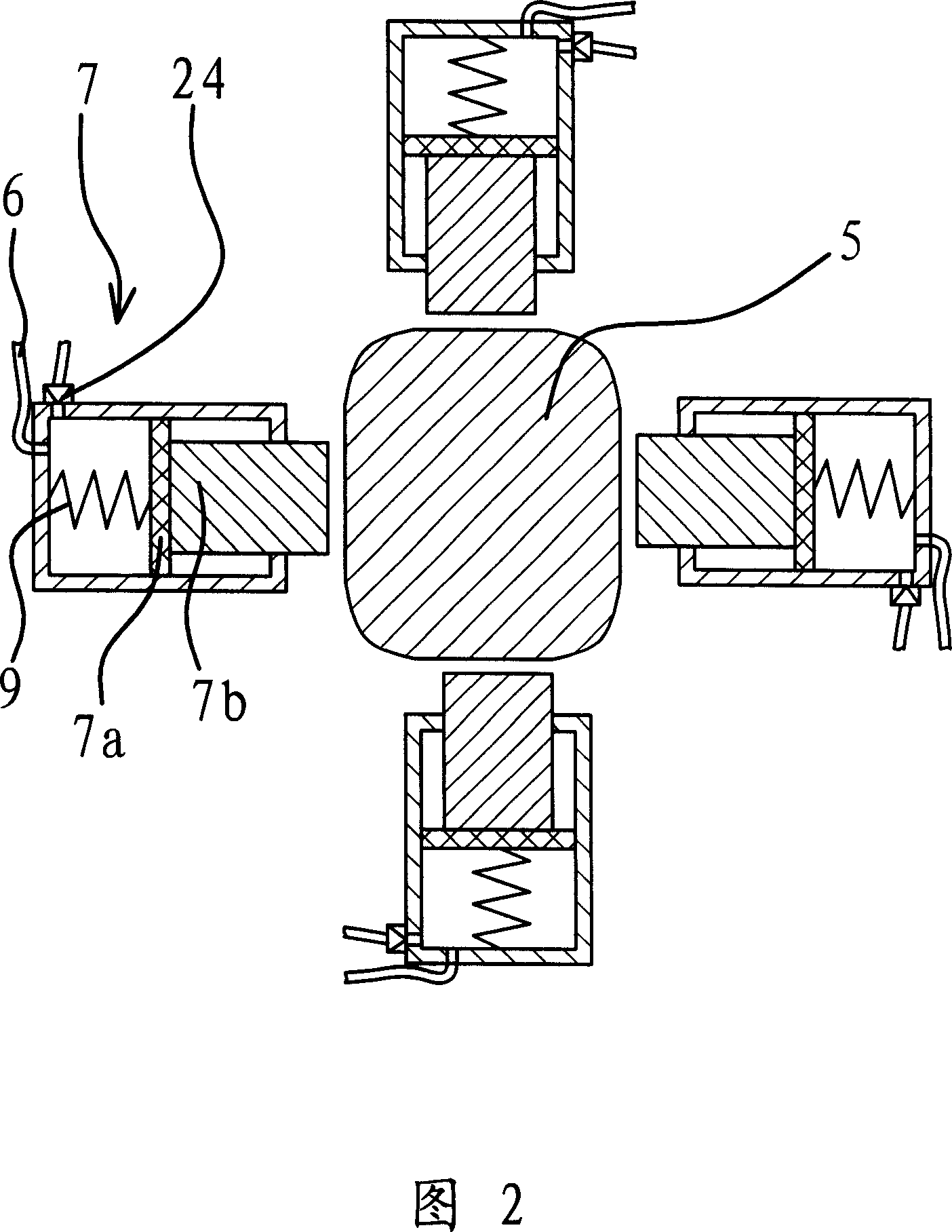
[0040] As shown in Figure 2, the linkage mechanism is a piston 7a and a piston rod 7b. The piston 7a is installed in the hydraulic cylinder 7...

Embodiment 2

[0052] As shown in Figure 4, the structure and principle of this embodiment are basically the same as that of Embodiment 1, the difference is that the return spring 9 is sleeved on the piston rod 7b, and the two ends of the return spring 9 are respectively fixedly connected to the piston 7a And on hydraulic cylinder 7, see as shown in Figure 3. It can be seen that the piston rod 7b has a tendency to move outwards due to the tension of the return spring 9, and when the swing block 5 is separated from the piston rod 7b, the piston rod 7b can automatically reset.

Embodiment 3

[0054] The structure and principle of this embodiment are basically the same as that of Embodiment 1. The difference is that the above-mentioned transmission mechanism also includes a sub-support 21 arranged in the buoy 1. The sub-support 21 is provided with a rotatable transmission shaft 22, the transmission shaft 22 is provided with sprocket three 12, and sprocket three 12 and sprocket one 10 are socketed with transmission chain two 11, and between described sprocket three 12 and transmission shaft 22, be provided with the unit that makes transmission shaft 22 one-way rotations. To the device, the transmission shaft 22 is also fixedly connected with a sprocket four 13, and the sprocket four 13 and the sprocket two 11 are sleeved with a drive chain three 16, as shown in Figures 5 and 6.

[0055] When the hydraulic motor 8 is in operation, the first sprocket 10 rotates, and the second sprocket 15 can drive the third sprocket 12 to rotate. Under the action of the one-way device,...


PUM


Abstract

The invention provides a wave power generating device, belonging to the electromechanical technology area, which solves problems that the prior wave power generating device is provided with shorter service life and worse stability. The wave power generating device comprises a closed float bowl with hollow cavity. In the float bowl a support and a generator with rotating shaft are set. Conductors connected with the generator passes through the float bowl. A swinging block is connected on the float bowl. There are a hydraulic cylinder and motor connected with each other by pipes in the float bowl. There is a linkage mechanism between the hydraulic cylinder and the swinging block. A transmission mechanism is set between the hydraulic motor and the rotary shaft of generator. The invention is provided with long service life and high working stability.

Description

technical field [0001] The invention belongs to the field of electromechanical technology, and relates to a generating device for generating electricity by using ocean waves. Background technique [0002] The undulating waves contain enormous energy, and this energy is inexhaustible. Therefore, people have designed various power generation devices that utilize ocean waves to generate electricity. [0003] For example, the "wave power generation device" provided by Chinese Patent No. 200420097626.0 includes a support fixedly connected to the seabed, a swingable hull is supported on the support, and a swingable generator is suspended in the hull. The rotating shaft of the generator is provided with a gear, and the inner bottom of the hull is provided with a rack with a certain radian, and the gear and the rack are meshed. [0004] When the hull swings with the waves, the relative position between the rack and the gear will change. Since the rack and the gear are meshed toget...

Claims


Application Information

Patent Timeline
IPC IPC(8): F03B13/22
CPCY02E10/38Y02E10/30
Inventor 张新金
Owner 张新金
Why Eureka
Try Eureka