Dry-type reactor
A dry-type reactor and pillar insulator technology, applied in the direction of preventing/reducing unwanted electric/magnetic effects, etc., can solve the problems of uneven electric field intensity at the coil end, burning of insulation defects of wire turns, and easy occurrence of shock discharge. , to achieve the effect of reducing inductance, avoiding discharge and ensuring stability
- Summary
- Abstract
- Description
- Claims
- Application Information
AI Technical Summary
Problems solved by technology
Method used
Image
Examples
Embodiment 1
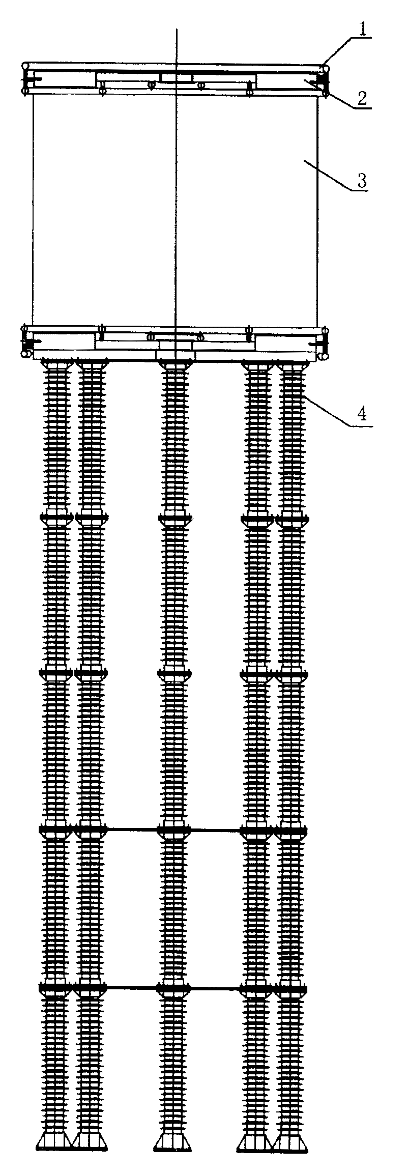
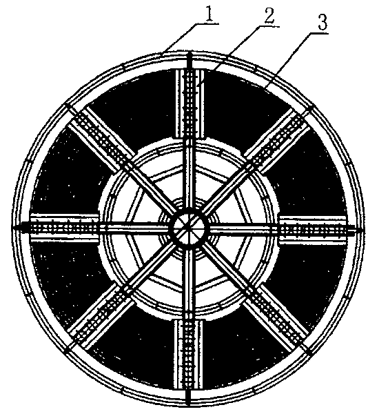
[0029] Embodiment 1: as figure 1 , figure 2 As shown, the structure of the present invention includes a coil 3, a shielding device 1 and a post insulator device 4, the two ends of the coil 3 are symmetrically equipped with a shielding device 1, and the two shielding devices 1 are connected by micelles, and the micelles are placed inside the coil. The number is determined by the short-circuit strength of the coil. A post insulator device 4 is installed at the lower part of the shielding device 1 at the lower end of the coil.
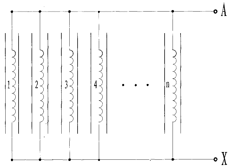
[0030] The coil 3 of the present invention includes an encapsulation 5 and an airway strut 8, such as Figure 4 As shown, the encapsulation 5 is placed side by side by a number of insulated aluminum strands 29, and insulating micelles are placed on the end, inner diameter and outer diameter side of the seal to form a parallel structure of multi-layer wires, such as image 3 As shown; the upper and lower envelope ends 6 of the envelope 5 are sealed into...
Embodiment 2
[0036] Embodiment 2: as figure 1 , figure 2 As shown, the structure of the present invention includes a coil 3, a shielding device 1 and a post insulator device 4. The shielding device 1 is symmetrically installed at both ends of the coil 3, and the two shielding devices 1 are connected by micelles. The micelles are placed inside the coil, and at one end of the coil A post insulator device 4 is installed on the lower part of the shielding device 1 .
[0037] Coil 3 of the present invention such as Figure 4 As shown, the structure is the same as that of the coil in Example 1. When the airway width H between the coils enclosing 5 is 30 mm, the upper base a of the trapezoid is 6 mm, and the lower base b is 15 mm, as Image 6 shown. The inner layer insulating film 10, the outer layer insulating film 12 and the insulating layer 11 of the aluminum stranded wire adopt heat-resistant class F class insulating materials according to different voltage levels.
[0038] Such as Fig...
Embodiment 3
[0042] Embodiment 3: as figure 1 , figure 2 As shown, the structure of the present invention includes a coil 3, a shielding device 1 and a post insulator device 4. The shielding device 1 is symmetrically installed at both ends of the coil 3, and the two shielding devices 1 are connected by micelles. The micelles are placed inside the coil, and at one end of the coil A post insulator device 4 is installed on the lower part of the shielding device 1 .
[0043] Coil 3 of the present invention such as Figure 4 As shown, the structure is the same as that of the coil in Example 1. When the airway width H=25mm between the coils enclosing 5, the upper base a of the trapezoid is 3 mm, and the lower base b is 6 mm, as Image 6 shown. The inner layer insulating film 10, the outer layer insulating film 12 and the insulating layer 11 of the aluminum stranded wire adopt heat-resistant class B, F, H class insulating materials according to different insulating temperature classes.
[00...
PUM
 Abstract
Description
Claims
Application Information
 - R&D
- Intellectual Property
- Life Sciences
- Materials
- Tech Scout
- Unparalleled Data Quality
- Higher Quality Content
- 60% Fewer Hallucinations
Browse by: Latest US Patents, China's latest patents, Technical Efficacy Thesaurus, Application Domain, Technology Topic, Popular Technical Reports.
© 2025 PatSnap. All rights reserved.Legal|Privacy policy|Modern Slavery Act Transparency Statement|Sitemap|About US| Contact US: help@patsnap.com


