
Thin film transistor substrate and method of manufacturing the same and mask for manufacturing thin film transistor substrate

A substrate and mask technology, which is applied in the field of masks for manufacturing thin film transistor substrates, and can solve problems such as residual images

Active Publication Date: 2007-08-08
SAMSUNG DISPLAY CO LTD
View PDF0 Cites 24 Cited by
  • Summary
  • Abstract
  • Description
  • Claims
  • Application Information

AI Technical Summary

Problems solved by technology

[0005] However, since such a TFT has a region where electrons can move between the drain and the source when the TFT is turned off, an off-current occurs
Therefore, there is a problem that an afterimage may be generated if the off-state current is increased

Method used


Image

  • Thin film transistor substrate and method of manufacturing the same and mask for manufacturing thin film transistor substrate
  • Thin film transistor substrate and method of manufacturing the same and mask for manufacturing thin film transistor substrate
  • Thin film transistor substrate and method of manufacturing the same and mask for manufacturing thin film transistor substrate

Examples


Embodiment Construction

[0073] Hereinafter, exemplary embodiments of the present invention will be described in detail with reference to the accompanying drawings. However, the present invention is not limited to the embodiments, but can be implemented in various forms. These examples are provided for illustrative purposes only, so that those skilled in the art will more fully understand the scope of the present invention.

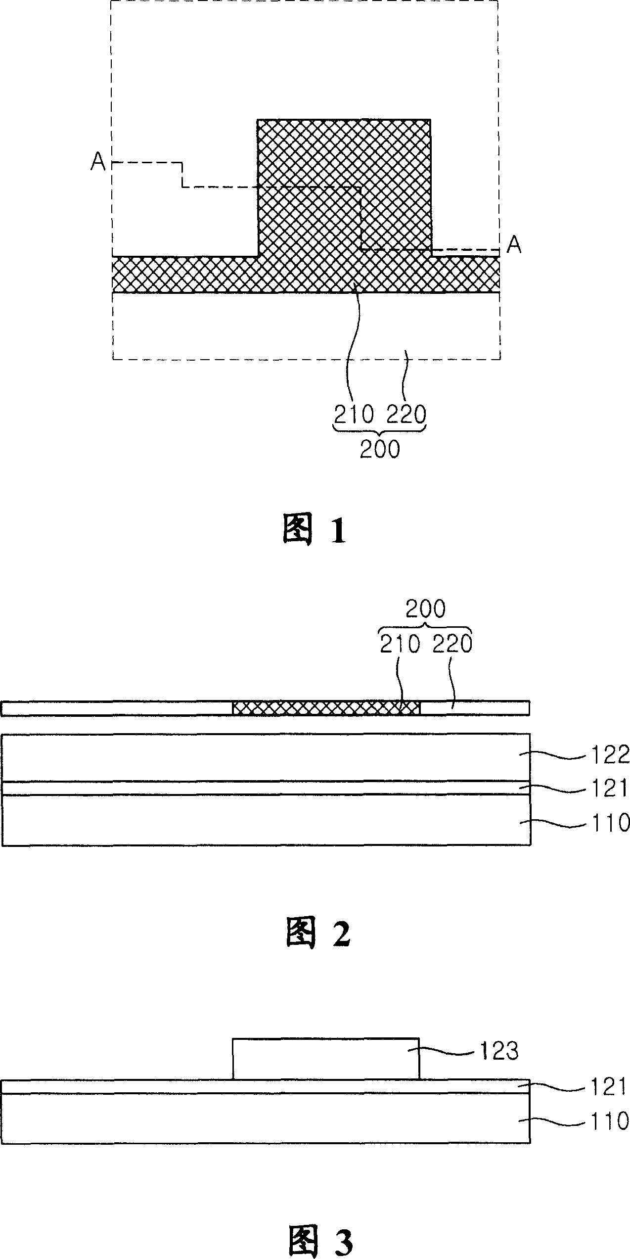
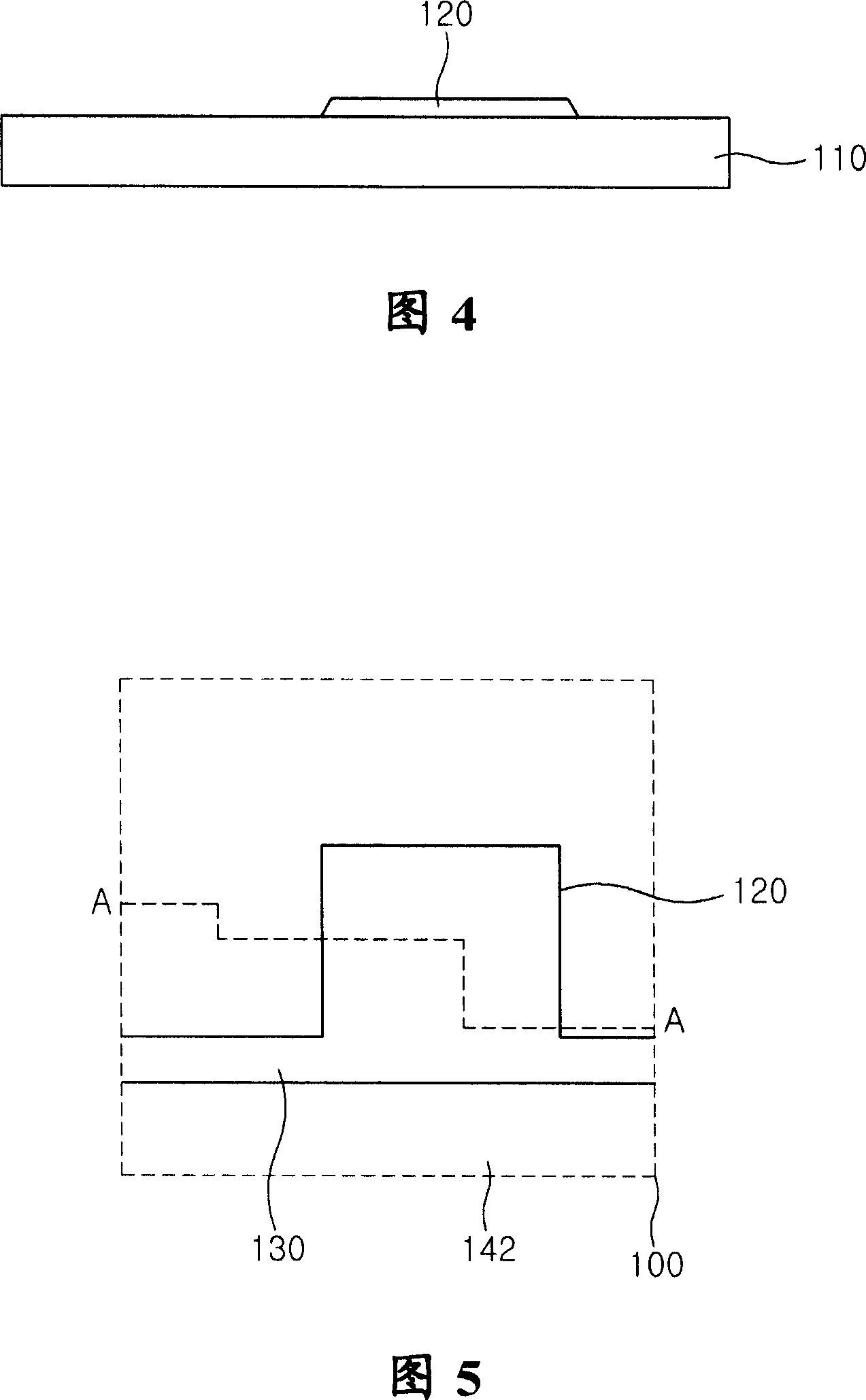
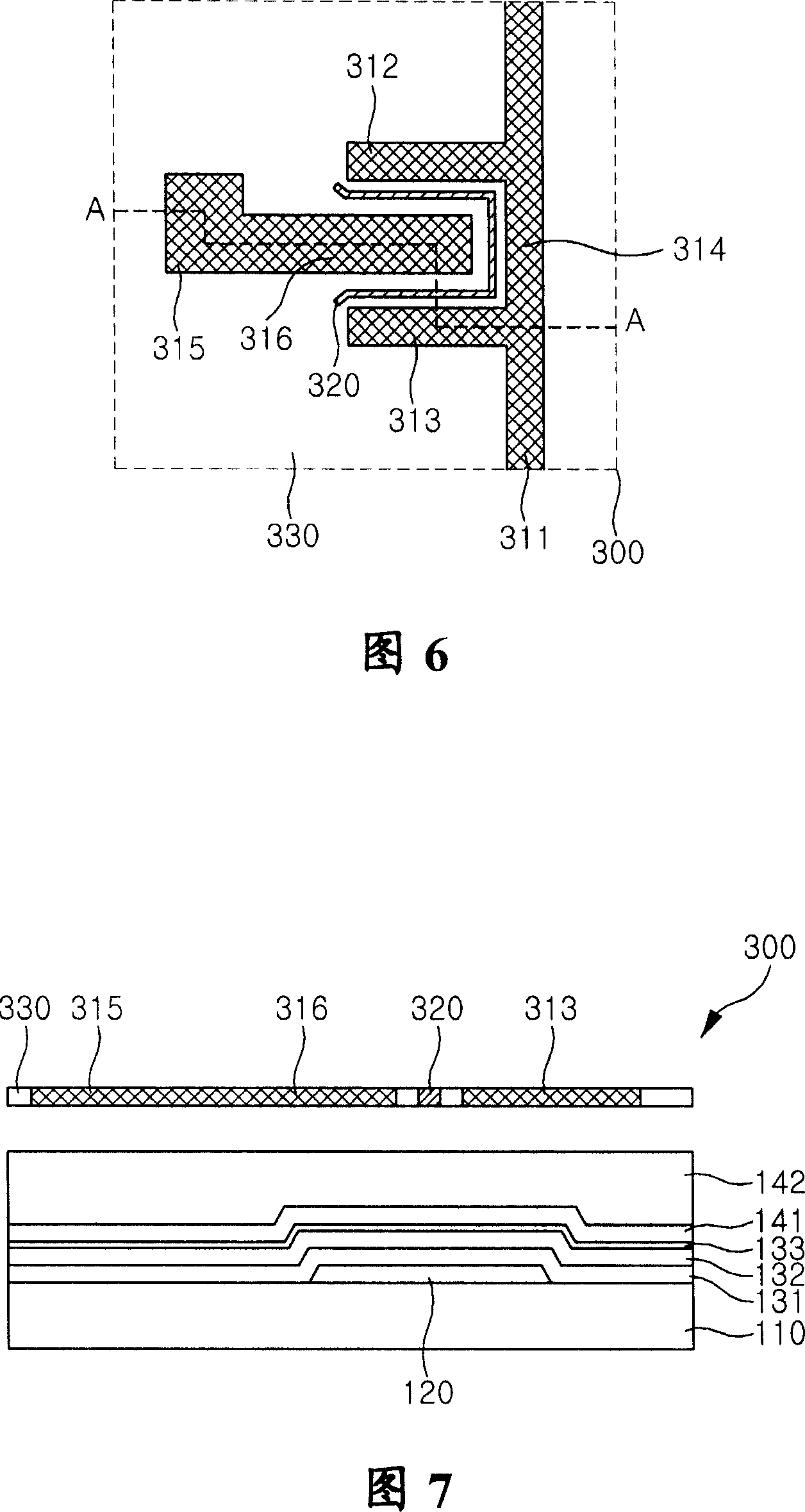
[0074] 1 is a plan view of a mask for forming a gate electrode according to an embodiment of the present invention, FIGS. 2 to 4 are cross-sectional views taken along line A-A in FIG. 1 to illustrate the formation of the gate electrode, and FIG. 5 is a view thereon A plan view of the substrate on which the gate electrode is formed.

[0075] Next, the formation of the gate electrode will be described with reference to FIGS. 1 to 5 . As shown in FIG. 2 , firstly, a first conductive film 121 is formed on the transparent insulating substrate 110 , and then a first photosensitive fi...


PUM


Abstract

A thin film transistor substrate, wherein the moving area of electrons between source and drain electrodes of a thin film transistor (TFT) is minimized, the moving distance of electrons is increased, and the sizes of capacitors defined by a gate electrode together with the respective source and drain electrodes are identical to each other so that an off current generated when the TFT is off can be minimized; a method of manufacturing the thin film transistor substrate; and a mask for manufacturing the thin film transistor substrate. Accordingly, it is possible to minimize an off current induced due to a phenomenon of electron trapping by light.

Description

technical field [0001] The present invention relates to a thin film transistor substrate, a method for manufacturing the thin film transistor substrate, and a mask for manufacturing the thin film transistor substrate. More particularly, the present invention relates to a thin film transistor capable of minimizing off-current of the thin film transistor. Background technique [0002] In general, a liquid crystal display (LCD) includes: a thin film transistor substrate on which pixel electrodes, storage capacitors, and thin film transistors (TFTs) for switching each pixel, etc. are formed; a common electrode substrate on which a common electrode is formed etc.; and the liquid crystal sealed between these two substrates. In an LCD, a voltage is applied between these two substrates to drive the liquid crystal to control light transmittance to display images. [0003] In such an LCD, a plurality of gate lines and a plurality of source lines are formed on a transparent glass sub...

Claims


Application Information

Patent Timeline
IPC IPC(8): H01L27/12H01L21/84G03F1/14G03F1/00
CPCH01L27/1288C02F1/70
Inventor 林都基李钟焕李洪雨金容照李庸羽
Owner SAMSUNG DISPLAY CO LTD
Learn More