Signal processing method of laser radar based on empirical mode decomposition

An Empirical Mode Decomposition and lidar technology, which is applied in the field of lidar signal processing, can solve the problems of signal characteristic scale jump, inability to clearly show the inherent nature of signal frequency process, and affect the effect of EMD method filtering, etc.

Inactive Publication Date: 2007-08-15
ANHUI INST OF OPTICS & FINE MECHANICS - CHINESE ACAD OF SCI
View PDF0 Cites 22 Cited by
  • Summary
  • Abstract
  • Description
  • Claims
  • Application Information

AI Technical Summary

Problems solved by technology

The problem is that if the selected neighborhood is too small, the filtering effect will be poor; if the neighborhood is too large, the inverted part of the signal will be smoothed.
[0031] However, when there is a strong inversion of the signal, or when the characteristic scale of the signal changes suddenly, using the EMD method to decompose the signal directly will cause modal aliasing
The modal aliasing phenomenon refers to the information obtained by decomposing an IMF that contains the IMF obtained after screening. Due

Method used


Image

  • Signal processing method of laser radar based on empirical mode decomposition
  • Signal processing method of laser radar based on empirical mode decomposition
  • Signal processing method of laser radar based on empirical mode decomposition

Examples


Embodiment Construction

[0097] See attached picture.

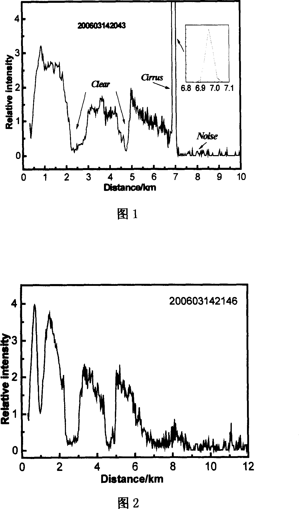
[0098] As shown in Figure 1, the layered distribution of signal strength is obvious, the echo signal of the boundary layer is strong, the fluctuation is small, and the signal-to-noise ratio is high; there is a clean layer between 2-3km and 4-5km, and a layer appears at 7km Thin cirrus clouds; due to the effect of cirrus clouds, the area after 7km is basically noise.

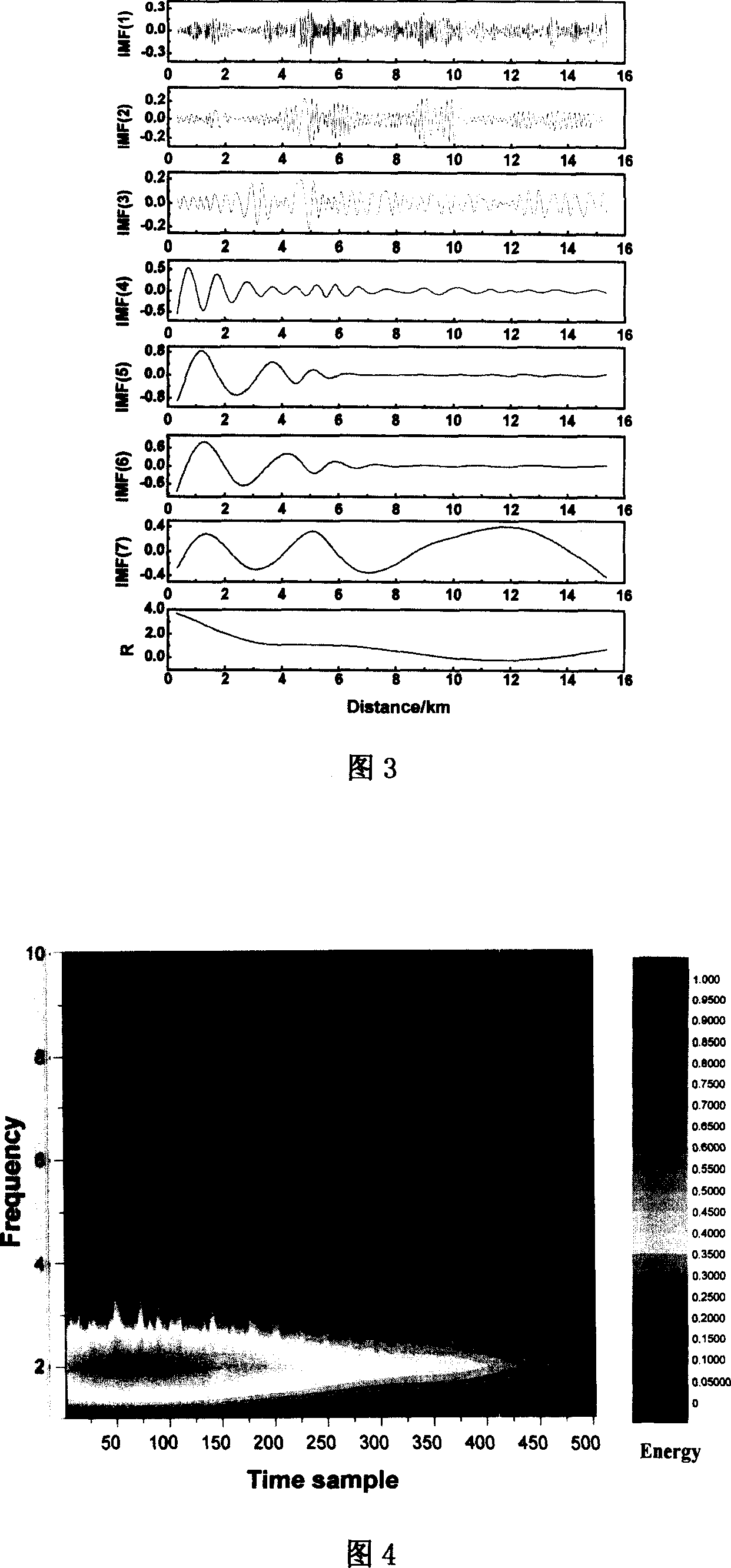
[0099] As shown in Figure 4, in the Hilbert time spectrum, the local and overall characteristics of the signal can be investigated in both the time domain and the frequency domain. It can be seen from the figure that the lidar signal is a low-frequency signal, and the energy of the signal shown in Figure 2 is mainly distributed within the range from the boundary layer to 6km.

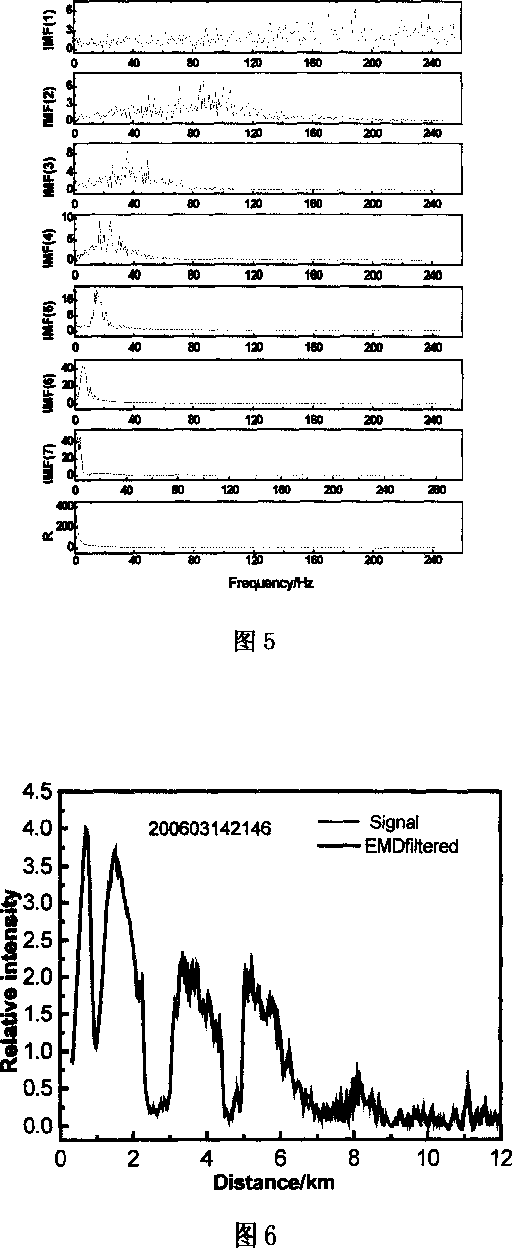
[0100] Figure 7 (a) shows the effect of the signal filtered by the EMD method. It can be seen from the figure that due to the existence of cirrus clouds, when the signal is decomposed by the EMD method, a mi...


PUM


Abstract

This invention discloses one laser radar signal process method based on experience, which aims for laser radar signal and experience module analysis and combines small wave exchange theory and statistic test theory; using central limit theory and Late rules to test the random of the signal intensity; testing signal inverse part to keep analysis method without experience with remaining part using experience analysis method.

Description

technical field [0001] The invention relates to a laser radar signal processing method. In particular, it is suitable for situations where there is an inversion of the lidar signal. technical background [0002] The laser radar signal received by the photoelectric detector, the laser radar equation determines the main factors of the signal, the laser radar equation can be expressed as the following form: [0003] P ( r ) = P t kr - 2 [ β m ( r ) + β a ( r ) ] exp { - 2 ...

Claims


Application Information

Patent Timeline
IPC IPC(8): G01S7/48G01S7/486G01S17/00
Inventor 孙东松周小林沈法华王邦新夏海云董晶晶李颖颖
Owner ANHUI INST OF OPTICS & FINE MECHANICS - CHINESE ACAD OF SCI
Why Eureka
Try Eureka