The circuit device of the power grid harmonious radio detector and its working method

A wireless detection and circuit device technology, applied in the direction of instruments, signal transmission systems, spectrum analysis/Fourier analysis, etc., can solve the problem that the voltage signal of the high-voltage power grid cannot be directly obtained, and the harmonic situation of the high-voltage line cannot be truly reflected. Not exactly the same problem, to achieve the effect of improving safety and reliability, simple structure and low cost

Inactive Publication Date: 2007-08-15
HOHAI UNIV CHANGZHOU
View PDF4 Cites 12 Cited by
  • Summary
  • Abstract
  • Description
  • Claims
  • Application Information

AI Technical Summary

Problems solved by technology

[0005] At present, the harmonic detection on the high-voltage grid line usually uses the detection of the harmonic content of the voltage at the PT line terminal of the substation to indirectly reflect the harmonic situation on the line. Due to the complex load of the line, the harmonic conditions between the high-voltage line and the PT line terminal of the substation are not complete. Similarly, the use of harmonic conditions at the PT line end of the substation cannot truly reflect the harmonic conditions on the high-voltage line. The best way to accurately measure the harmonic content on the high-voltage grid line is to measure directly
[0006] Chinese patent application 89105302.6 discloses a "power system harmonic measurement method and measuring instrument", Chinese patent application 92106527.2 discloses a "electric power harmonic measurement method with an electronic computer", and Chinese patent application 98110414.2 discloses a "power system harmonic measurement method". System Harmonic Quantitative Measurement Method and Measuring Instrument", Chinese patent application 200310105446.2 discloses a "method and measuring instrument for measuring factory harmonics". detection, it is impossible to directly obtain the voltage signal of the high-voltage power grid, and the above-mentioned existing technologies are not suitable for use

Method used


Image

  • The circuit device of the power grid harmonious radio detector and its working method
  • The circuit device of the power grid harmonious radio detector and its working method
  • The circuit device of the power grid harmonious radio detector and its working method

Examples


Embodiment 1

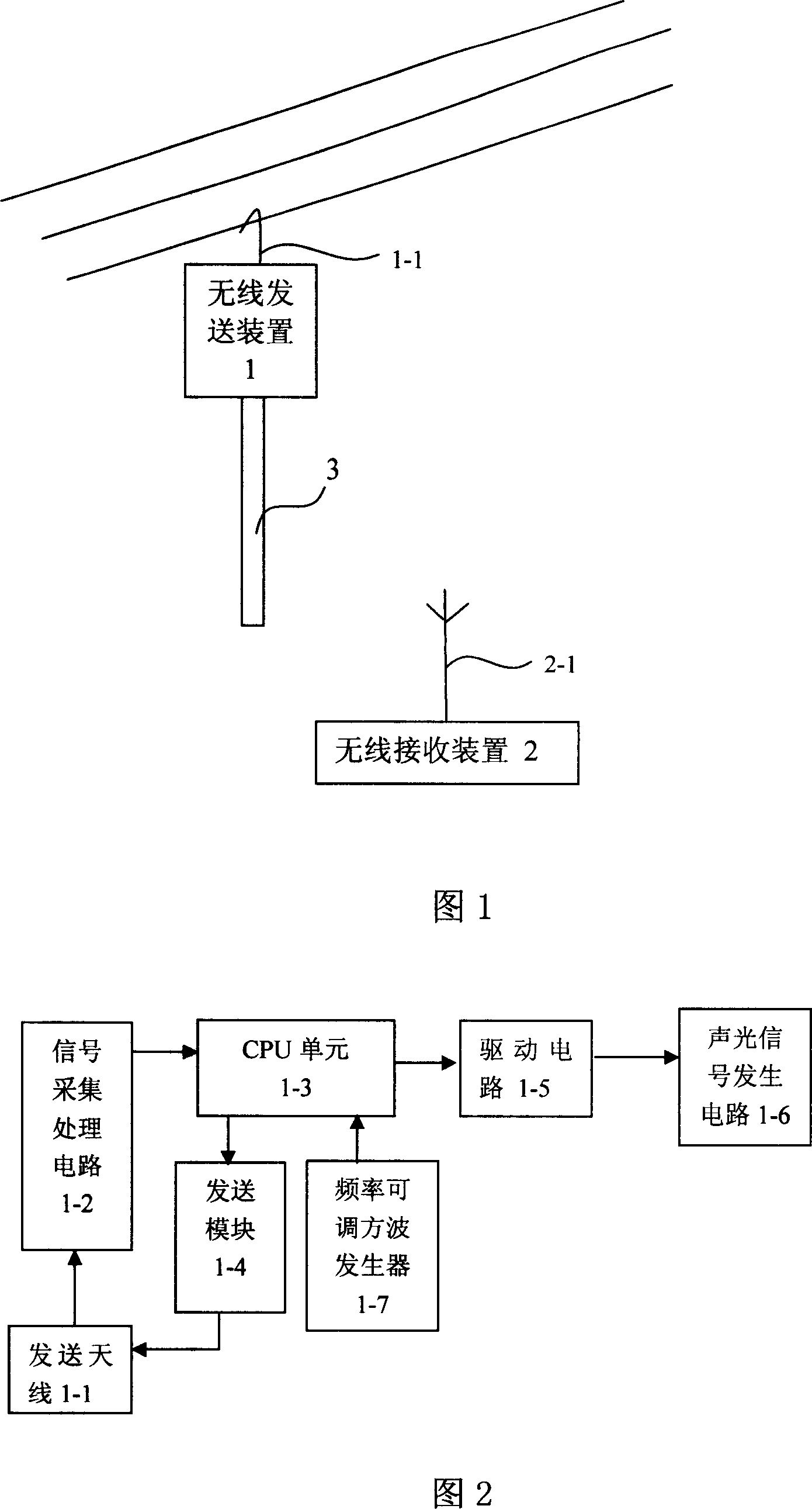
[0031] See Fig. 1, the circuit device of the grid harmonic wireless detector of this embodiment includes: a wireless transmitting device 1 for collecting grid voltage signals by the field strength method and a wireless receiving device for handheld display of harmonic content in the measured grid voltage 2.

[0032] As shown in Fig. 2, the wireless transmission device 1 includes: an electrode 1-1, a signal acquisition and processing circuit 1-2, a first CPU unit 1-3 and a transmission module 1-4, a driving circuit 1-5, and an acousto-optic signal generation circuit 1- 6 and frequency adjustable square wave generators 1-7.

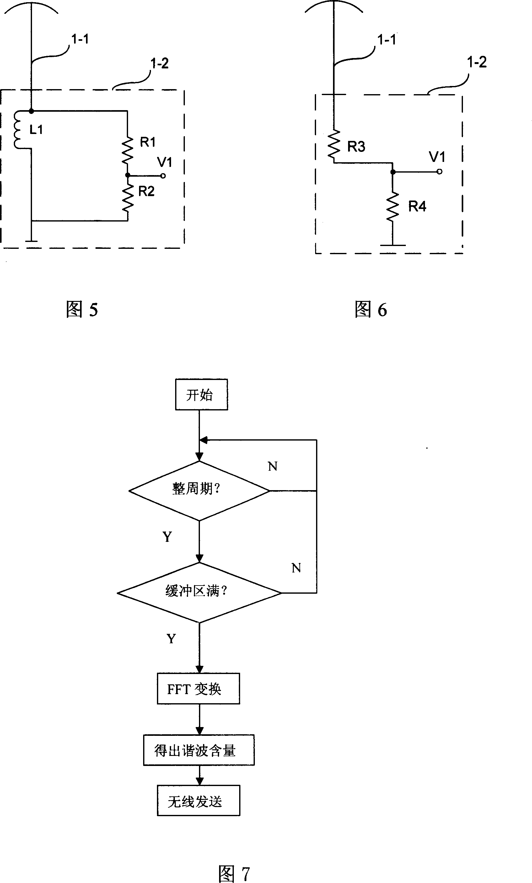
[0033]The electrode 1-1 is a metal conductor, and the outer surface of the metal conductor can be wrapped with an insulating layer. The electrode 1-1 is electrically connected to the high-voltage grid voltage signal input terminal of the signal acquisition and processing circuit 1-2; the grid voltage signal output terminal of the signal acquisition and pro...


PUM


Abstract

This invention relates to one electricity resonance wave wireless tester circuit device and its work method, wherein, the device comprises wireless send device to collect electricity voltage signals and wireless receive device to display the resonance content; in wireless send device, electrode is near high voltage conductive wires to collect the voltage in contact or non-contact types; signal collection process is to couple field voltage to test voltage; CPU unit analyzes the each wave content according to the test voltages; send module is to modulate the content information to be sent from electrode; wireless receive device is to receive and display each wave content.

Description

technical field [0001] The invention relates to the technical field of high-voltage detection, in particular to a circuit device and a working method of a grid harmonic wireless detector. Background technique [0002] With the development of power electronics technology, the harmonic problems brought by power electronic devices pose a potential threat to the safety, stability and economic operation of the power system, and have a great impact on the surrounding electrical environment. Harmonics are considered to be a major public hazard of the power grid. At the same time, it also hinders the development of power electronics technology. Therefore, the research on harmonic problems in power systems has been gradually paid attention to. [0003] Harmonic hazards can be attributed to: 1) consumption of reactive power and increased line loss; 2) causing equipment overload, reducing the insulation level of equipment, accelerating insulation aging and even causing fires; 3) reduci...

Claims


Application Information

Patent Timeline
Patent Type & Authority Applications(China)
IPC IPC(8): G08C17/02G08C17/00G01R23/16
Inventor 张金波胡钢
Owner HOHAI UNIV CHANGZHOU
Why Eureka
Try Eureka