Main upper roll driver for plate bending machine
A plate rolling machine and main drive technology, which is applied in transmission devices, gear transmission devices, mechanical equipment, etc., can solve the problems of high cost, long axial dimension of motor and planetary reducer in series, and large volume of output stage gears. It achieves the effects of convenient manufacturing and maintenance, reduced volume and weight, and low cost
- Summary
- Abstract
- Description
- Claims
- Application Information
AI Technical Summary
Problems solved by technology
Method used
Image

Examples
Embodiment 1
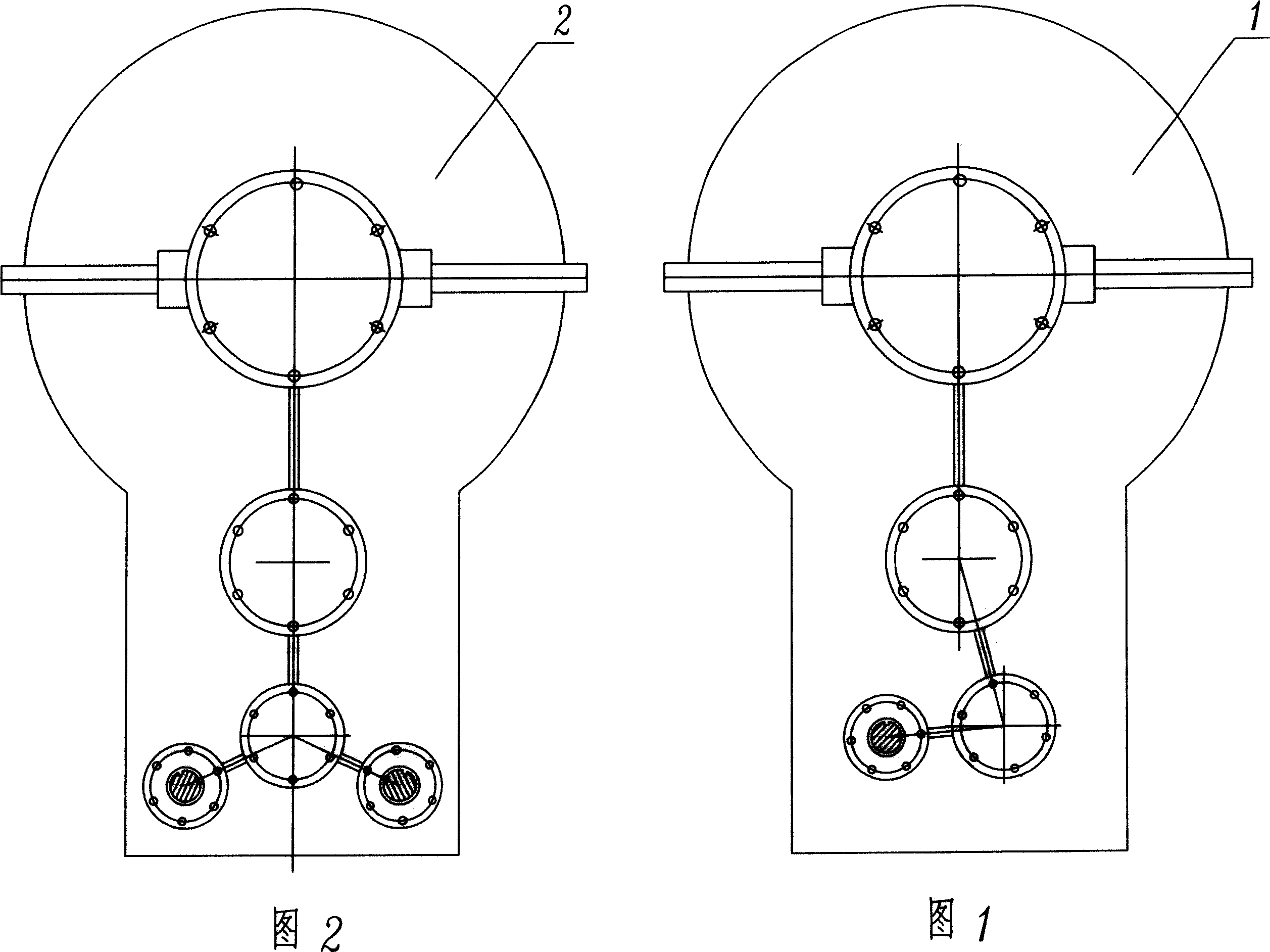
[0026] As shown in Figure 1, the main transmission device of the upper roll of the plate rolling machine is composed of a reducer (that is, a three-stage parallel shaft single-input external gear reducer 1) and a power device. The large gear of the output stage of the machine is fixedly connected to the upper roller, and the input shaft of the reducer (in Figure 1, the input shaft is a section view, and the power device is not shown) is connected with the output shaft of the power device, which is an electric motor or an oil motor The reducer includes a reducer case and a 3-stage parallel-shaft external mesh transmission gear. The reducer case is connected with the upper roller through the rolling bearings on both sides of the output stage gear of the reducer. The 3-stage parallel shaft external mesh transmission gear is located in the reducer case. , the output stage is provided with a small gear, the pinion gear of the output stage is located under the large gear of the outpu...
Embodiment 2
[0029] As shown in Figure 2, the main transmission device of the upper roller of the plate rolling machine is composed of a reducer (that is, a three-stage parallel shaft input stage double-input external mesh gear reducer 2) and a power device, and the upper roller performs the pressing and feeding movement , the large gear of the output stage of the reducer is fixedly connected to the upper roller, the input shaft of the reducer (the two input shafts in Fig. The device is an electric motor or an oil motor; the reducer includes a reducer box, a 3-stage parallel shaft external meshing transmission gear, the reducer box is connected with the upper roller through the rolling bearings on both sides of the large gear of the output stage of the reducer, and the 3-stage parallel shaft external meshing The transmission gear is located in the reduction box, the output stage has a small gear, the output stage pinion gear is located under the output stage large gear, and the output stage...
Embodiment 3
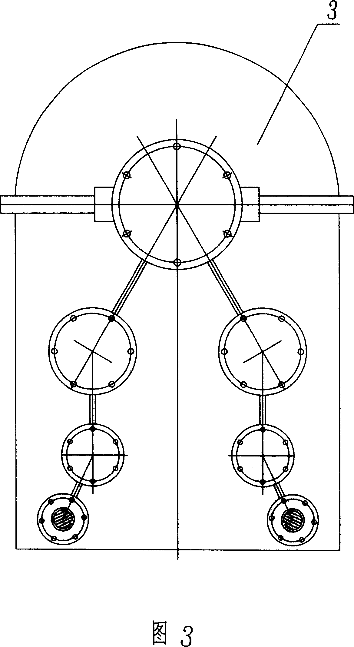
[0032] As shown in Figure 3, the main transmission device of the upper roll of the plate rolling machine includes a reducer (that is, a three-stage parallel shaft output stage double pinion external gear reducer 3) and a power device, and the output stage of the reducer is fixed. Connected to the upper roller, the input shaft of the reducer (the 2 input shafts in Figure 3 are cross-sectional views, and the 2 power devices are not shown) is connected with the output shaft of the power device, and the power device is an electric motor or an oil motor; the reducer Including the reducer box, 3-stage parallel shaft external meshing transmission gear, the reduction box is connected with the upper roller through the rolling bearings on both sides of the large gear of the output stage of the reducer, the 3-stage parallel shaft external meshing transmission gear is located in the reducer box, the output stage There are two output stage pinion gears, the two output stage pinion gears are...
PUM
 Abstract
Description
Claims
Application Information
 - R&D
- Intellectual Property
- Life Sciences
- Materials
- Tech Scout
- Unparalleled Data Quality
- Higher Quality Content
- 60% Fewer Hallucinations
Browse by: Latest US Patents, China's latest patents, Technical Efficacy Thesaurus, Application Domain, Technology Topic, Popular Technical Reports.
© 2025 PatSnap. All rights reserved.Legal|Privacy policy|Modern Slavery Act Transparency Statement|Sitemap|About US| Contact US: help@patsnap.com