Circular mobile tooth and small tooth difference variable-speed drive device

A technology of variable speed transmission and less tooth difference, which is applied in the direction of gear transmission, transmission, belt/chain/gear, etc., which can solve the problems of low load capacity, limitation of transmission accuracy and meshing performance of movable tooth reducer, and inability to fully meet the requirements

Inactive Publication Date: 2009-02-11
赵大庆
View PDF2 Cites 4 Cited by
  • Summary
  • Abstract
  • Description
  • Claims
  • Application Information

AI Technical Summary

Problems solved by technology

However, due to the limitation of standard bearing accuracy, rated load capacity and cage life, and the limitation of processing eccentric shaft technology level, the tolerance of eccentricity has a sensitive influence on the backlash change law of the conjugate tooth profile, which is directly related to the activity. With the improvement of the motion accuracy and transmission performance of gear transmission, the shock wave composed of standard bearings and eccentric shafts has many problems in terms of accuracy, performance and life, and cannot fully meet the needs of high-performance transmission components - push rod movable tooth transmission. The requirements of the key technology limit the further improvement of the transmission accuracy and meshing performance of the movable gear reducer. The movable pair between the push rod movable tooth and the radial guide groove has become a problem for improving the transmission efficiency and The key to life, so there is low load capacity, the general input power does not exceed 30kW, and high machining accuracy is required for the inner curve profile tooth shape
[0007] CN2531173Y discloses a circular movable tooth planetary reducer with a larger diameter of the rotating arm bearing and a larger diameter of the distribution circle of the pin shaft of the output mechanism. Difficulty in manufacturing and maintenance

Method used


Image

  • Circular mobile tooth and small tooth difference variable-speed drive device
  • Circular mobile tooth and small tooth difference variable-speed drive device
  • Circular mobile tooth and small tooth difference variable-speed drive device

Examples


Embodiment Construction

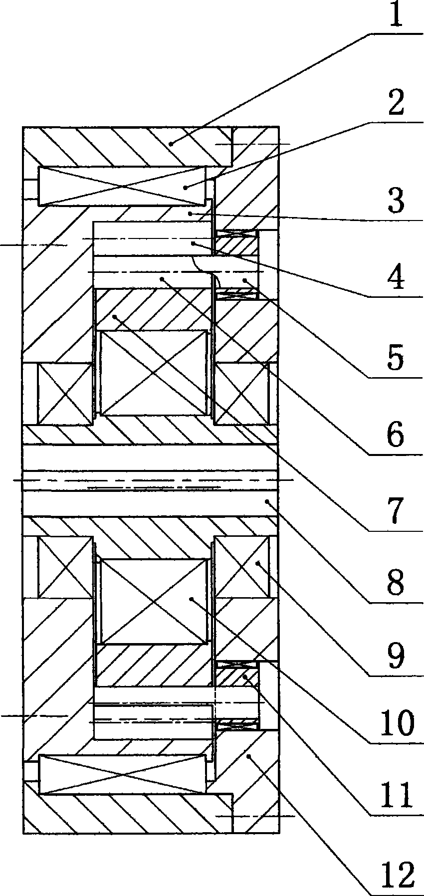
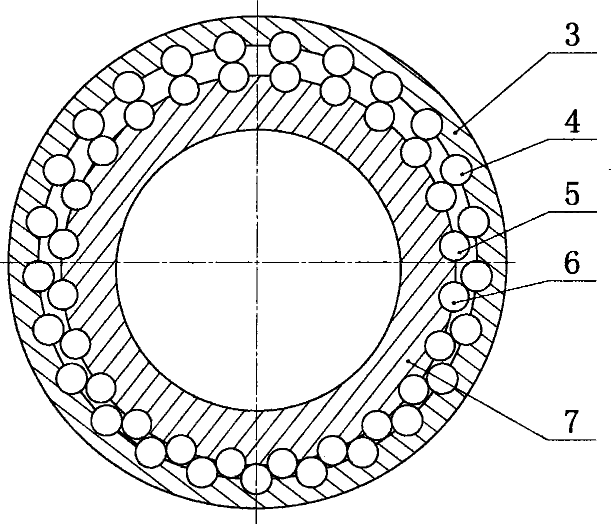
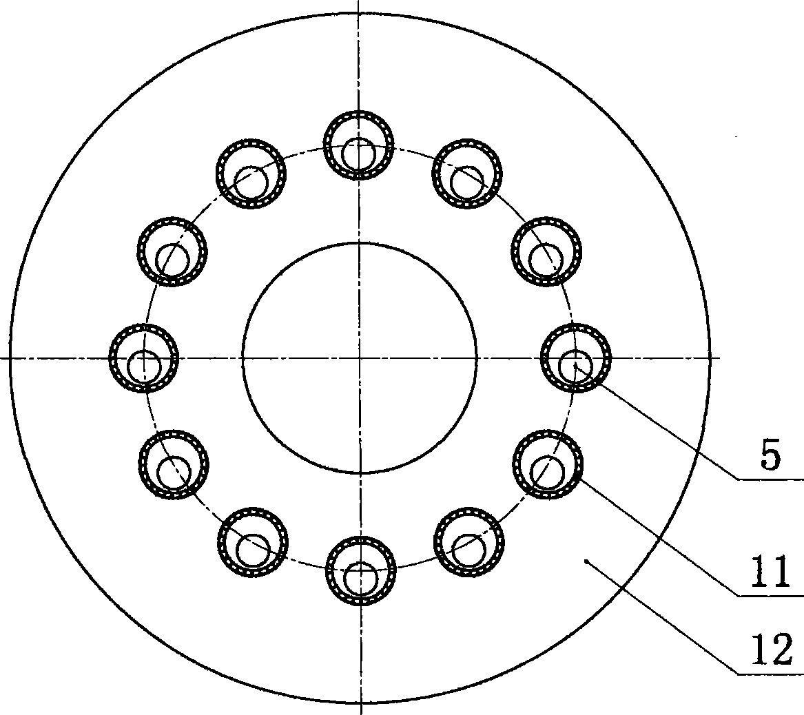
[0027] The following will refer to Figure 1 to Figure 6 First to fourth embodiments of the present invention will be described. The same reference numerals for parts will be used to denote the same parts in these embodiments. Therefore, for each embodiment, repeated descriptions will be omitted, and structural differences will be focused on.

[0028] Refer below Figure 1 to Figure 3 , the figure shows the first embodiment of the present invention, the circular movable tooth less tooth difference variable speed transmission device is composed of an eccentric mechanism, a less tooth difference mechanism, and a hole pin type force transmission mechanism; the eccentric shaft 8 is supported by two bearings 9 On the transmission ring 3 and the pin hole end cover 12, the transmission ring 3 is supported on the outer ring 1 through the bearing group 2, and the inner gear ring 7 is supported on the eccentric shaft 8 through the arm bearing 10; the inside of the transmission ring 3 ...


PUM


Abstract

The invention discloses a circular oscillating tooth variable speed driving device with small teeth difference, consisting of an outer ring, a bearing pack, a driving ring, driving ring oscillating teeth, long oscillating teeth, short oscillating teeth, a ring gear, an eccentric shaft, a bearing, a rotary arm bearing, an eccentric bearing, a pin hole end cap, a pin tooth sleeve, a counter balance and a load balancing ring. In the driving device, the driving ring and the ring gear are meshed with small teeth difference, the meshed gear form is a cylindrical surface which can replace the traditional involute or cycloid, and the cylinder can rotate freely for convex-concave matching; a hole-pin type force transferring mechanism is adopted, a pin hole disk is arranged at the side and is integrated with the end cap, pins are selected from a plurality of cylindrical oscillating teeth and the pins and the teeth are integrated; the driving ring is an output mechanism. The whole shape of compact structure can carry out constant ratio variable transmission between input and output as a common rolling bearing can.

Description

technical field [0001] The invention relates to a small-tooth-difference transmission mechanism, in particular to a circular movable tooth small-tooth-difference transmission device. Background technique [0002] The present invention is proposed for planetary transmission with small tooth difference. There are many types of planetary transmission with small tooth difference. Small tooth difference planetary transmission, etc., and are still developing, and new structural types are constantly being designed and proposed. [0003] The involute gear planetary transmission with small tooth difference has a wide range of transmission ratio in theory, but in practice, the transmission efficiency is very low when the transmission ratio is large, so this transmission is mostly used for small power transmission at present. [0004] Cycloid planetary transmission with less tooth difference requires high manufacturing precision, requires special processing equipment, and the processi...

Claims


Application Information

Patent Timeline
Patent Type & Authority Applications(China)
IPC IPC(8): F16H3/44
Inventor 赵大庆
Owner 赵大庆
Why Eureka
Try Eureka