Machine tool

A technology of machine tools and linear motors, applied in the direction of metal processing machinery parts, large fixed members, driving devices, etc., to achieve the effect of preventing bad conditions

Inactive Publication Date: 2007-08-22
FANUC LTD
View PDF5 Cites 7 Cited by
  • Summary
  • Abstract
  • Description
  • Claims
  • Application Information

AI Technical Summary

Problems solved by technology

However, if the selection is based on the assumed external force, there is a problem that a linear motor that generates a force larger than the force required for the axis feed during actual machining and an amplifier that drives the linear motor have to be selected.

Method used


Image

  • Machine tool
  • Machine tool
  • Machine tool

Examples


Embodiment Construction

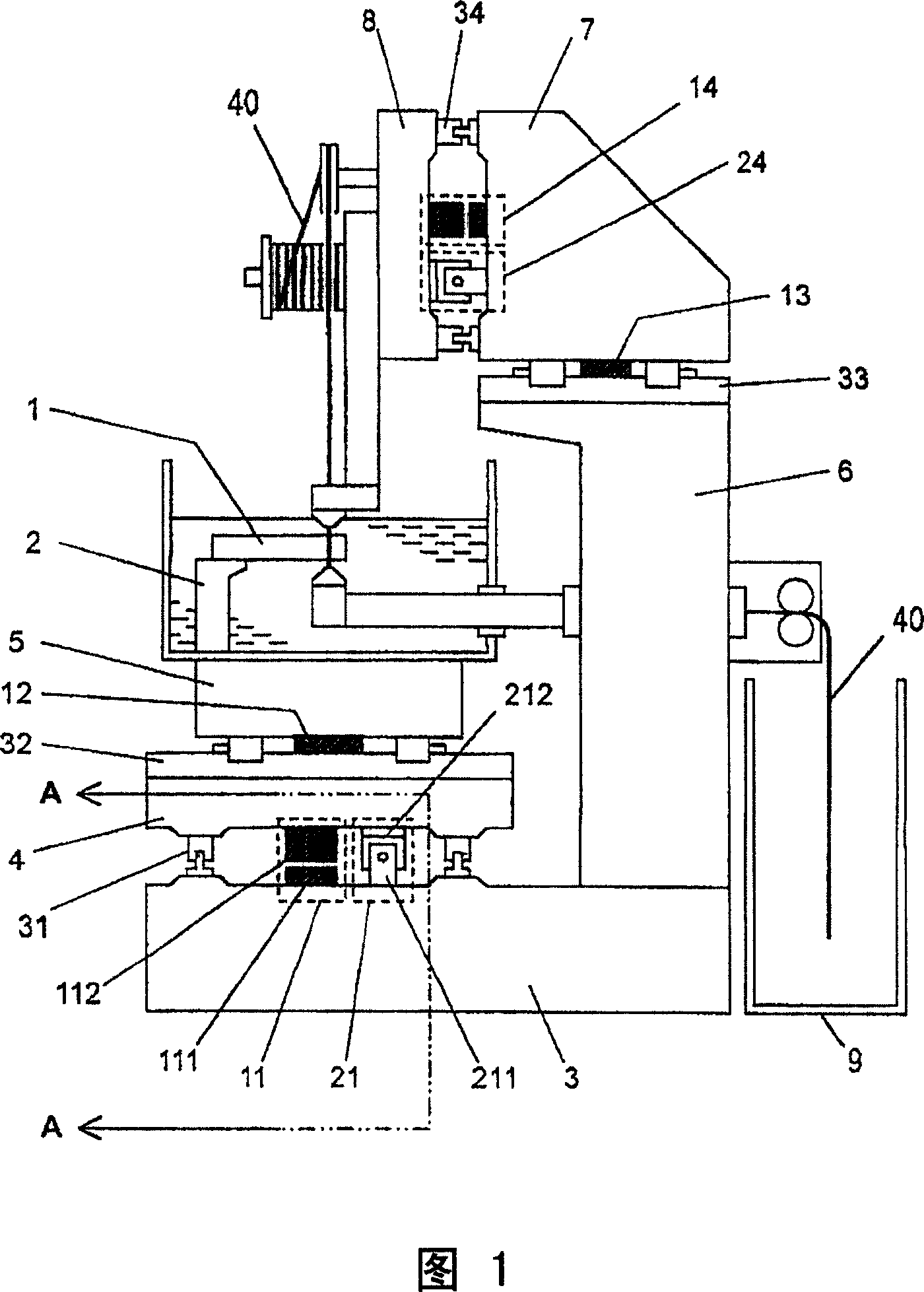
[0022] Hereinafter, an example in which the machine tool is a wire electric discharge machine will be described as one embodiment to which the present invention is applied. Especially in wire electric discharge machines, the possibility of applying a large external force to the shaft feeder during processing is low, and the possibility of applying a large external force in preparation for processing such as setting the workpiece on the workpiece placement table high. Therefore, in the present embodiment, it is necessary to prevent the linear motor from being overloaded due to a large external force acting during the processing preparation.

[0023] FIG. 1 is a schematic diagram of a wire electric discharge machine according to this embodiment.

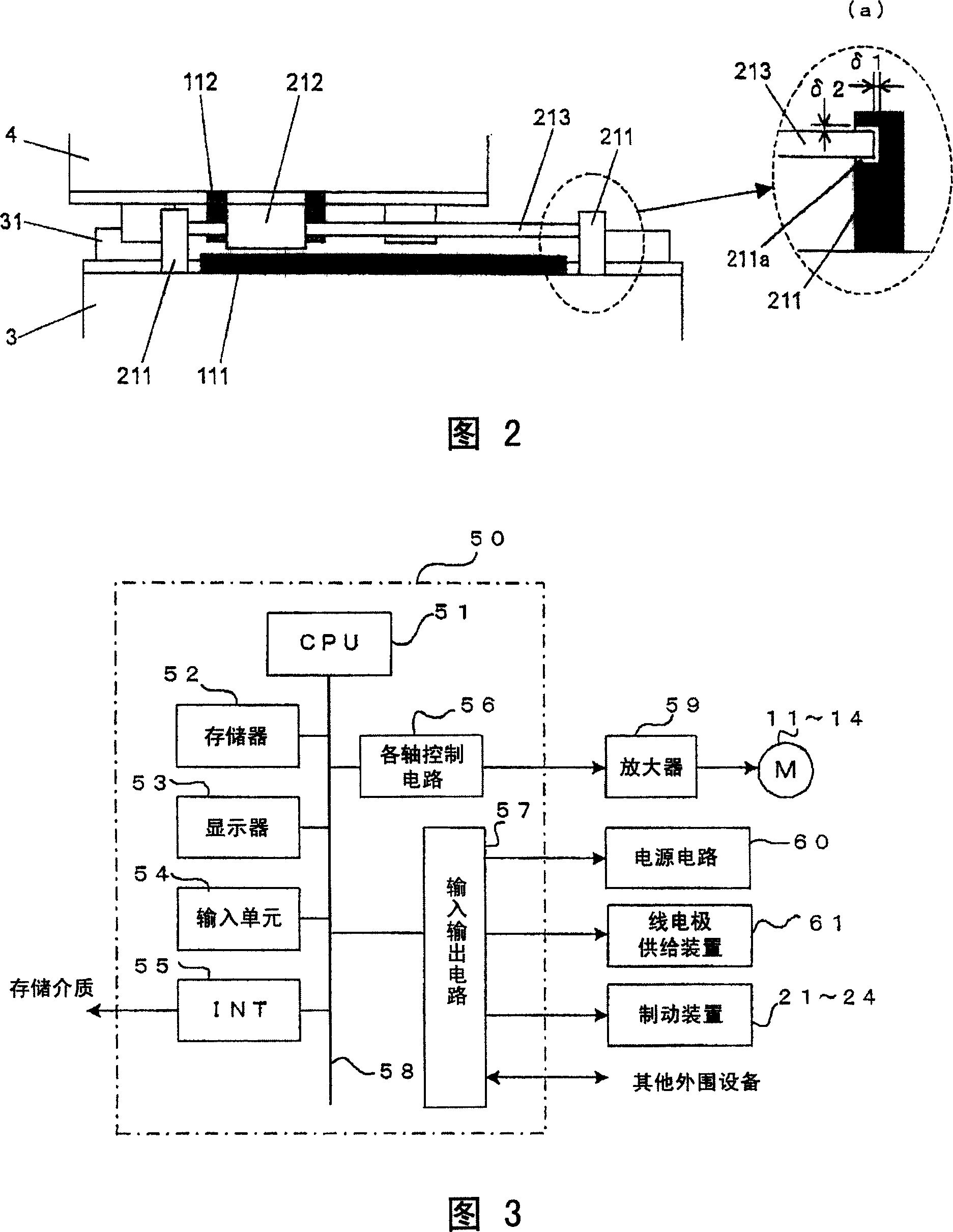
[0024] A saddle 4 is installed on the bed 3 of the wire electric discharge machine, so that the saddle 4 can move along a direction perpendicular to the paper surface of FIG. 1 through a linear moving guide rail 31 . In addition, the...


PUM


Abstract

The invention relates to a machine tool. Brake apparatus is arranged in parallel with linear motors. The brake apparatus is switched on to lock a movable shaft when the linear motors are not excitated. During a non-processing operation without manual feeding instructions, when the linear motors are excitated and a processing signal is cut off, the brake apparatus is switched on to lock the movable shaft. Even if the motors are excitated but not in a processing state and without the manual feeding instructions, the movable shaft can also be locked.

Description

technical field [0001] The invention relates to machine tools with linear motors driving movable axes. Background technique [0002] Conventionally, in machine tools and wire-cut electric discharge machines, rotary motors have been used as drive sources for driving movable shafts. Generally, the rotary motion of the servo motor linearly moves the movable shaft by a conversion mechanism that converts the rotary motion of a ball screw / nut mechanism etc. into linear motion. [0003] In recent years, machine tools using direct-acting linear motors as drive sources for feed axes have also been put into practical use. [0004] For example, it is known from JP-A-61-226225, JP-A-63-2626, and JP-A-8-318433 that a linear motor is used as a drive source for a feed shaft of a wire electric discharge machine. In addition, it is also known from JP-A-6-297286 that a linear motor is used to drive the feed axis of a machine tool. In this Japanese Patent Laid-Open No. 6-297286, it is also ...

Claims


Application Information

Patent Timeline
Patent Type & Authority Applications(China)
IPC IPC(8): B23Q1/26B23Q5/52B23Q5/20B23H7/26
CPCB23Q5/28B23H7/26B23Q1/28
Inventor 喜多佑树樱井章博
Owner FANUC LTD
Why Eureka
Try Eureka