Condenser

A condenser and subcooling technology, which is applied in the direction of evaporator/condenser, refrigerator, refrigeration components, etc., can solve the problems of poor heat transfer surface area efficiency of heat dissipation pipes, increase condenser volume, sacrifice condenser performance, etc., and achieve improved Effects of heat dissipation, quantity reduction, and requirement reduction

Inactive Publication Date: 2007-08-22
AIR INT THERMAL SYST R&D (SHANGHAI) CO LTD
View PDF0 Cites 6 Cited by
  • Summary
  • Abstract
  • Description
  • Claims
  • Application Information

AI Technical Summary

Problems solved by technology

[0011] 3. The efficiency is poor in the effective use of the heat transfer surface area of ​​the heat dissipation tube of the condenser
[0014] 2. The heat transfer coefficient is the highest (sensible heat + latent heat), and due to the phase change, there is a certain flow resistance;
This will inevitably increase the volume of the condenser, and the cost of production will also increase.
Or in order to control the volume and production cost of the condenser, the performance of the condenser can only be sacrificed

Method used


Image

  • Condenser
  • Condenser

Examples


Embodiment Construction

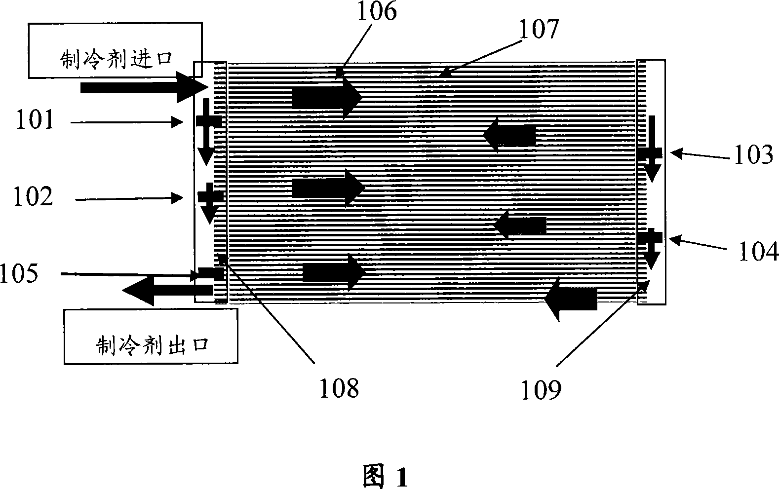
[0037] Please refer to FIG. 1 , which is a schematic structural diagram of the first embodiment of the present invention.

[0038] As shown in Figure 1, it is a non-supercooled condenser, including a number of regularly arranged radiating tubes 107, a first header 108 and a second header connected to the two ends of the radiating tubes and communicated therewith. 109. A refrigerant inlet and a refrigerant outlet are respectively arranged on the first header 108, and several baffles are arranged alternately in the two headers so that the refrigerant flows back from the inlet to the outlet in the condenser, and the baffles Among them, the partition 101, the partition 102, the partition 103 and the partition 104 are provided with through holes.

[0039] When the superheated steam of the refrigerant enters the first header 108 of the condenser, most of the superheated steam enters the heat dissipation pipe 107, that is, enters the desuperheating area, while a part of the superheat...


PUM


Abstract

The invention discloses a non-overcooling condenser. It includes many regular arranged cooling tubes which the two ends are connected with two collecting mains. The inlet and outlet of the refrigerating medium are all set on the collecting tube which is set with much clapboard to make the medium turn over. At least one through-hole is opened in at least clapboard beside the clapboard which is near to the outlet. Also the invention discloses an overcooling condenser which opens the plume in part clapboard. The diversion controller is used in the invention to reach the mixing flow effect of the medium in condenser; actually, it is a series and parallel condenser. The invention has improved the radiator effect but not increased the volume and decreased the flow resistance of the medium in over heat area.

Description

technical field [0001] The invention relates to a heat exchange device, especially a condenser. Background technique [0002] Condenser is a device that makes the high-temperature and high-pressure refrigerant compressed by the compressor exchange heat with the air through its outer wall to cool the refrigerant. Existing condensers are generally divided into non-supercooled and non-supercooled. supercooled type. [0003] The non-supercooled condenser includes a number of regularly arranged radiating pipes, two collecting pipes respectively connected to the two ends of the radiating pipes and communicating with them, and two collecting pipes are arranged on the collecting pipes as refrigerant inlet and outlet respectively. The openings of the two collecting pipes are staggered to arrange a number of partitions to make the refrigerant flow back from the inlet to the outlet in the condenser. [0004] The supercooled condenser includes a number of regularly arranged radiating ...

Claims


Application Information

Patent Timeline
Patent Type & Authority Applications(China)
IPC IPC(8): F25B39/04
Inventor 曾欣叶粮
Owner AIR INT THERMAL SYST R&D (SHANGHAI) CO LTD
Why Eureka
Try Eureka