
Driver fatigue detection alarm

A driver fatigue and alarm device technology, applied to alarms, instruments, automatic starting devices, etc., can solve problems such as false alarms, unreasonable structures, and immature technologies, and achieve low error, light weight, and strong anti-interference Effect

Inactive Publication Date: 2007-08-22
陈大冶 +1
View PDF0 Cites 16 Cited by
  • Summary
  • Abstract
  • Description
  • Claims
  • Application Information

AI Technical Summary

Problems solved by technology

However, due to the irrational structure of existing products and the immature technology, false positives, missed negatives, and wrong positives often occur in the actual application process, making it difficult to popularize existing driver fatigue alarms

Method used


Image

  • Driver fatigue detection alarm

Examples


Embodiment Construction

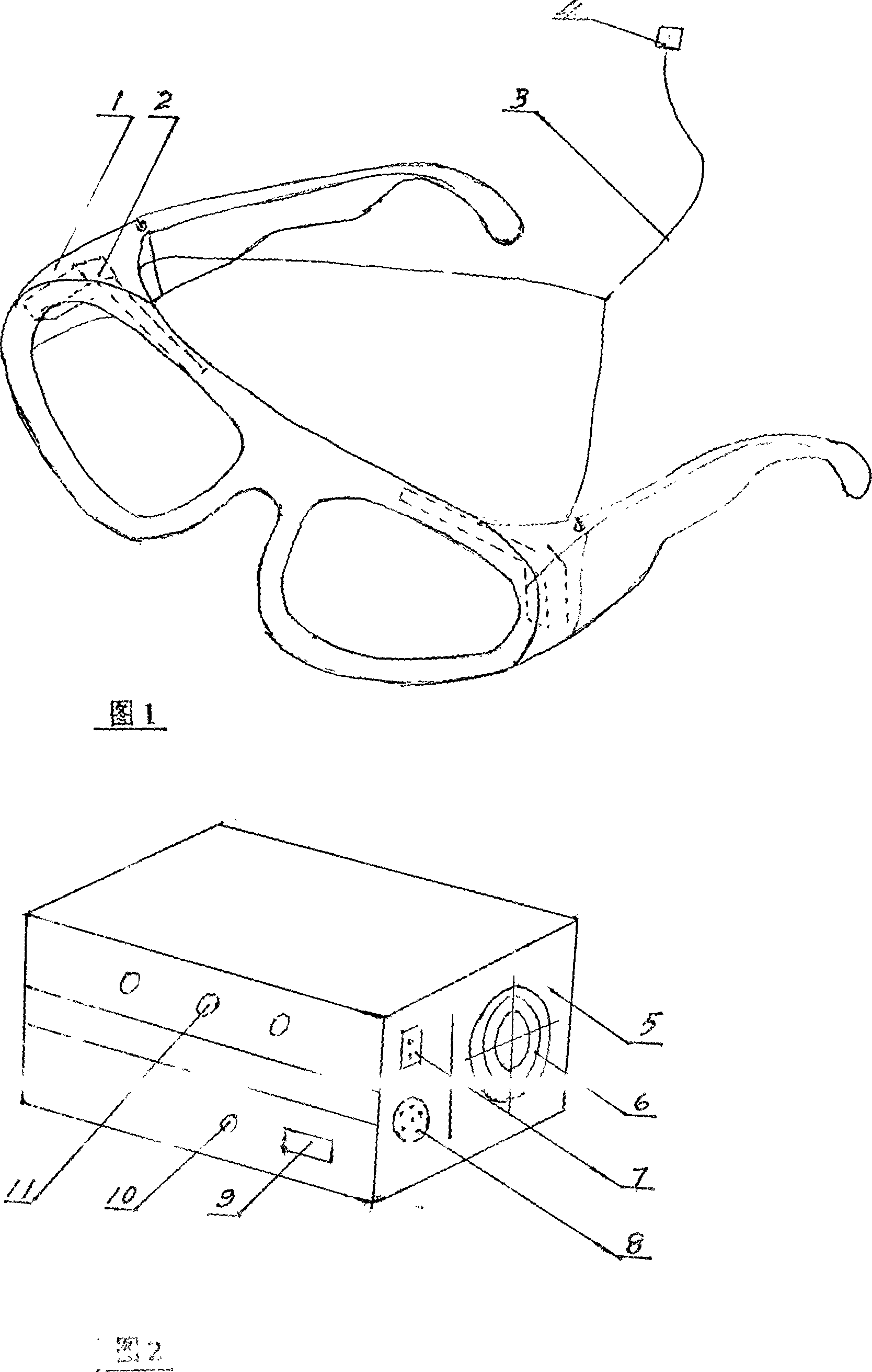
[0011] First, assemble the optical fiber sensor (1) on the side frames of the spectacle frame, and straighten the optical fiber (3) for use. Fix the chassis (5) of the intelligent control system device on the instrument platform of the car, connect the power supply and the optical fiber line for transmitting information, insert the optical fiber plug (4) on the glasses into the optical fiber socket (7), and then the driver Put on the glasses and conduct a power-on test. If the yellow and green lights flash alternately, it means that the system is operating normally. If the eyes are closed for 1 second, the red light will flash, and the tweeter will say "You are tired, take a rest!" Warning sound, if the eyes are closed for more than 1 second, it can be forced to stop. Prove like this, driver's fatigue detection alarm meets design requirement of the present invention


PUM


Abstract

This invention relates to an alarm for testing fatigue of drivers composed of a glass with a reflection fiber shift sensor and an intelligent control system, which takes the expression of fatigue of the eye part as the primary standard to set up a math model to monitor the flash frequency of eyelid, the close time, running of eye balls and pupil contraction and expansion so as to emit acousto-optical warning or force it stopping.

Description

Technical field: [0001] The invention relates to a driver fatigue detection and alarm device, which belongs to a traffic safety protection alarm device. The device has the functions of sound and light warning and forced parking for fatigue driving. Background technique: [0002] There are multiple driver fatigue alarms on the market, which have played a significant role in reducing traffic accidents. However, due to the unreasonable structure of existing products and immature technology, phenomena such as false positives, missed negatives, and wrong positives often occur in the actual application process, making existing driver fatigue alarms difficult to popularize. Therefore, the present invention discloses a driver fatigue detection and alarm device to meet market demands. Invention content: [0003] In order to overcome the shortcomings of the prior art, the invention discloses a driver fatigue detection and alarm device, which is composed of an optical fiber sensor ...

Claims


Application Information

Patent Timeline
IPC IPC(8): G08B21/06B60T7/12
Inventor 陈大冶陈大伟
Owner 陈大冶
Learn More