Electronic apparatus and introduction system into sample under test

A technology for electronic devices and objects to be tested, which is applied in the direction of radio detectors, endoscopes, electrical components, etc. in the body, can solve problems such as improper use, and achieve the effect of potential stability

Inactive Publication Date: 2007-08-22
OLYMPUS CORP
View PDF1 Cites 7 Cited by
  • Summary
  • Abstract
  • Description
  • Claims
  • Application Information

AI Technical Summary

Problems solved by technology

However, if a large-scale potential supply source is built into the receiving device, it will lead to an increase in the size of the receiving device, and it is especially difficult to use it in a portable structure such as a receiving device used in a capsule endoscope system. Inappropriate

Method used


Image

  • Electronic apparatus and introduction system into sample under test
  • Electronic apparatus and introduction system into sample under test
  • Electronic apparatus and introduction system into sample under test

Examples


Embodiment 1

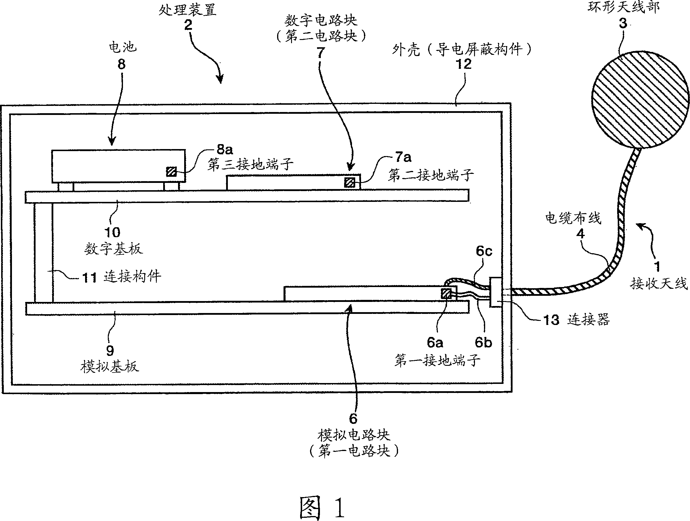
[0077] First, the electronic device of Embodiment 1 will be described. FIG. 1 is a schematic diagram showing the overall configuration of an electronic device according to the first embodiment. As shown in FIG. 1 , the electronic device according to the first embodiment includes: a receiving antenna 1 for receiving wireless signals; and a processing device 2 for performing predetermined reception processing on the wireless signals received by the receiving antenna 1 .

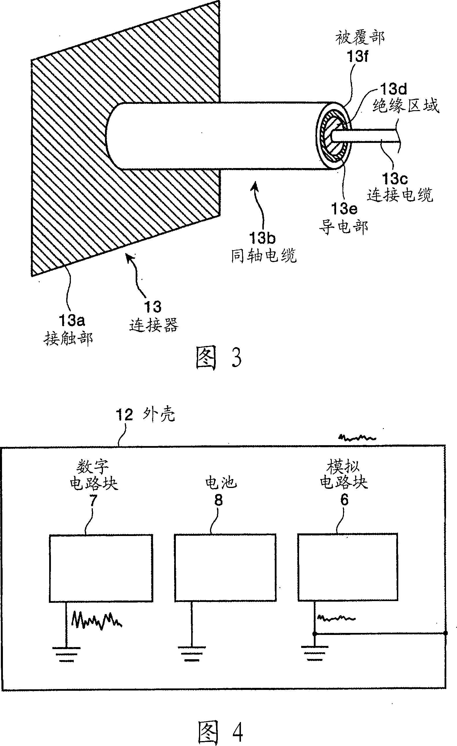
[0078] The receiving antenna 1 includes a loop antenna section 3 for receiving wireless signals, and a cable wiring 4 for transmitting signals received via the loop antenna section 3 to circuits inside the case 12 and the like. The loop antenna unit 3 has, for example, a structure in which helical conductive wiring is formed on the surface of a film-like base material, and has a function of receiving radio signals at the corresponding helical portion. In addition, the cable wiring 4 is used to electrically con...

Deformed example 1

[0103] Next, Modification 1 of the electronic device according to Embodiment 1 will be described. FIG. 5 is a schematic diagram showing a part of the configuration of the electronic device according to the first embodiment. As shown in FIG. 5 , a terminal 15 is arranged on the analog substrate 9 arranged inside the case 12 , and the terminal 15 is electrically connected to a first ground terminal 6 a (not shown in FIG. 5 ) provided in the analog circuit block 6 . .

[0104] Furthermore, a structure is adopted in which the ground potential of the analog circuit block 6 is supplied to the case 12 by electrically connecting the terminal 15 and the case 12 via the wire harness 16 . Specifically, predetermined screw holes are formed in advance on the terminal 15 and the housing 12, and the two ends of the wire harness 16 are arranged in conformity with the screw holes, and screwed and fixed by the screws 17 and 18, thereby connecting the terminal 15 and the housing. 12 is electri...

Deformed example 2

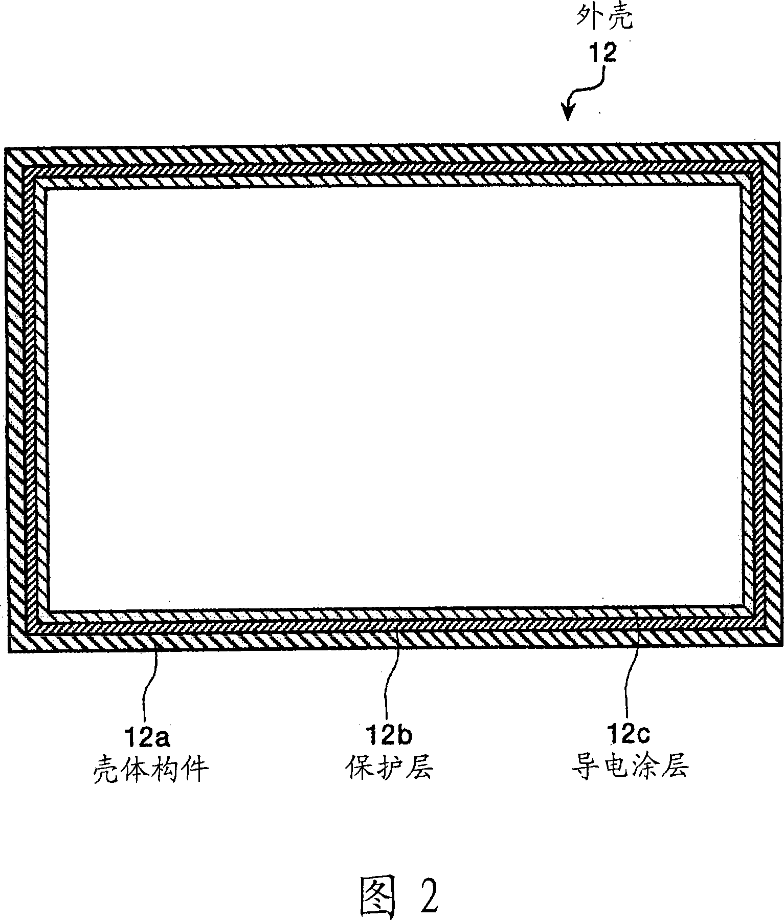
[0107] Next, Modification 2 of the electronic device according to Embodiment 1 will be described. FIG. 6 is a schematic diagram showing the configuration of an electronic device according to Modification 2. As shown in FIG. As shown in FIG. 6 , the electronic device according to Modification 2 has a structure in which a circuit board 21 is arranged in a housing 20 in a processing device 19 and an analog circuit block 6 is arranged on the circuit board 21 . Digital circuit block 7 and battery 8 . In addition, the electronic device according to Modification 2 has a structure in which the insulating mold layer 22 is formed so as to contain the circuit board 21 and the analog circuit block 6 arranged on the circuit board 21, and the The conductive molding layer 23 is formed so that the insulating molding layer 22 is contained therein.

[0108] Here, the insulating mold layer 22 does not include all of the circuit board 21 and the analog circuit block 6 arranged on the circuit bo...


PUM


Abstract

The present invention provides an electric device and a guide system for subject. The processing device (2) includes an analog circuit block (6), a digital circuit block (7), a casing (12) which houses elements including (6) and (7) and serves as a conductive shield member, and a connecting connector (13) which has functions, for example, of electrically connecting the casing (12) and a first ground terminal (6a) provided in the analog circuit block (6). Level of noise signals generated from the analog circuit block (6) is lower than the level of noise signals generated from the digital circuit block (7). Therefore, when the casing (12) is electrically connected to the first ground terminal (6a) provided in the analog circuit block (6), the casing (12) can maintain a stable potential thereby more effectively working as the conductive shield member. Thus, leakage of the noise signals generated at driving of internal electronic circuitry is effectively suppressed in an electronic apparatus such as a receiving apparatus.

Description

technical field [0001] The present invention relates to an electronic device including a plurality of circuit blocks, and a system introduced into a subject including a receiving device including a plurality of circuit blocks. Background technique [0002] In recent years, swallow-type capsule endoscopes have been proposed in the field of endoscopes. This capsule endoscope is provided with an imaging function and a wireless communication function. Capsule endoscope has the function of following the peristalsis of internal organs such as the stomach and small intestine in the body cavity after being swallowed by the subject (human body) for observation (inspection) and before it is naturally discharged. Movement, moving within it, and shooting in turn. [0003] While moving in the body cavity, the image data captured by the capsule endoscope inside the body is sequentially transmitted to the outside by wireless communication, received by an external receiving device, subjec...

Claims


Application Information

Patent Timeline
Patent Type & Authority Applications(China)
IPC IPC(8): A61B5/07H05K9/00A61B1/00
CPCH05K9/0039A61B5/07A61B1/041A61B2562/182A61B1/00016H05K9/0024
Inventor 本多武道
Owner OLYMPUS CORP
Why Eureka
Try Eureka