Cooling device pertaining to an electrical machine

A cooling device and cooling system technology, applied in the direction of cooling/ventilation devices, electromechanical devices, electrical components, etc., to achieve the effect of improving the cooling effect and the best cooling effect

Inactive Publication Date: 2007-08-22
SIEMENS AG
View PDF1 Cites 19 Cited by
  • Summary
  • Abstract
  • Description
  • Claims
  • Application Information

AI Technical Summary

Problems solved by technology

This type of cooling is designed for operating situations where motors are extremely problematic, without taking into account the fact that some critical duty cycle capability of the motor is not required for a particular use of the motor

Method used


Image

  • Cooling device pertaining to an electrical machine
  • Cooling device pertaining to an electrical machine
  • Cooling device pertaining to an electrical machine

Examples


Embodiment Construction

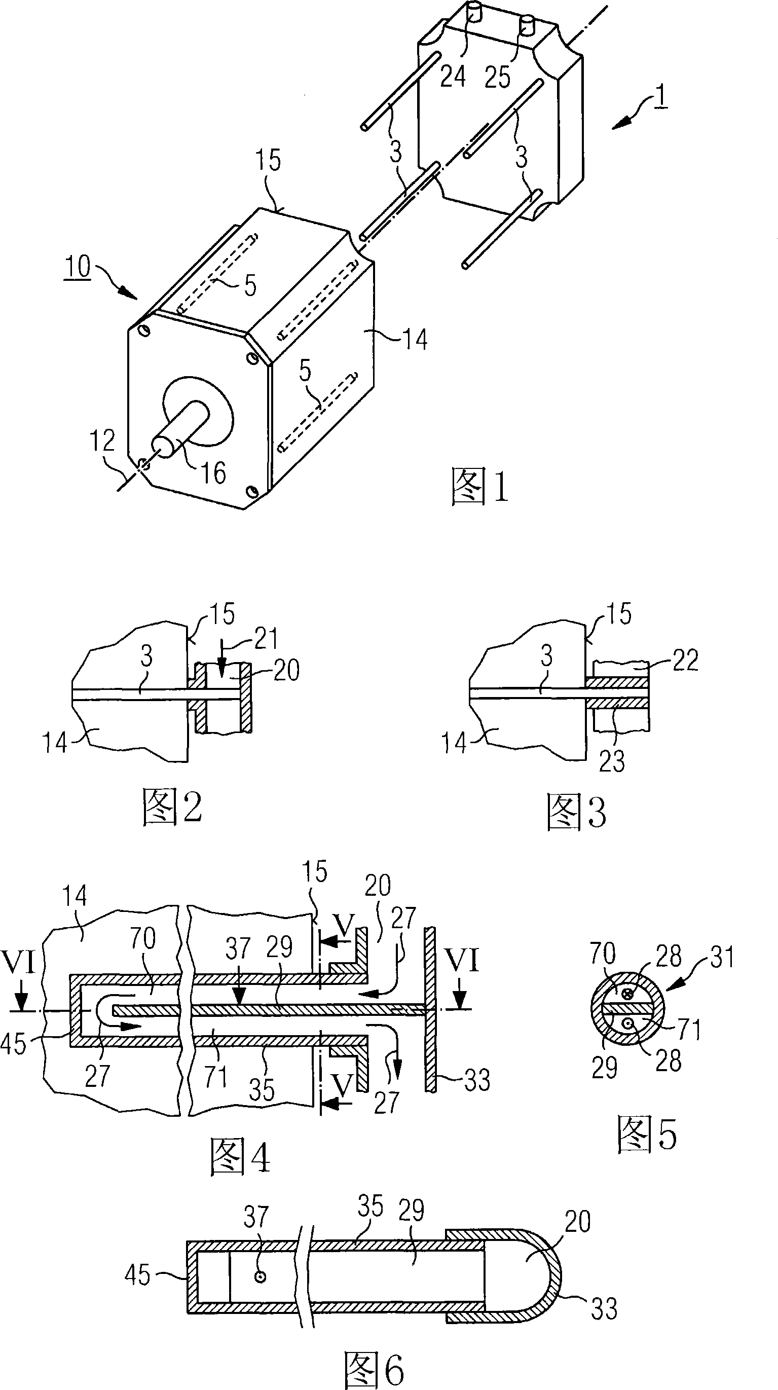
[0037] FIG. 1 shows an electric motor 10 . The electric machine 10 is a housingless rotating electric machine having an axis 12 . The electric machine 10 also has a shaft 16 and a stator 14 . A plurality of receiving channels 5 are arranged in the stator 14 . The receiving channel 5 is used to accommodate the rod-shaped heat conducting element 3 . Furthermore, FIG. 1 also shows a cooling device 1 . The cooling device 1 has connection pieces 24 and 25 . These connections are used, for example, to introduce or discharge cooling fluid or cooling air. The cooling device 1 also has a plurality of rod-shaped heat conducting elements 3 . The rod-shaped heat conducting element 3 is configured to be inserted into the receiving channel 5 . According to another design not shown in FIG. 1 , the rod-shaped heat-conducting element 3 is arranged on the stator 14 , wherein the rod-shaped heat-conducting element 3 protrudes outside an end face 15 of the motor 10 , wherein the rod-shaped ...


PUM


Abstract

The invention relates to a cooling device (1,2) pertaining to an electrical machine (10), said cooling device (1,2) comprising at least one rod-shaped heat-conducting means (3,4) for heat-conductive connection to the electrical machine (10). The invention also relates to an electrical machine (10) comprising a housing (18) and / or a stator (14), said housing (18) and / or stator (14) being applied to a cooling device (1,2) comprising a rod-shaped heat-conducting means (3,4) extending axially in relation to the electrical machine. Said heat-conducting means (3,4) is to be received by the stator (14) and / or the housing (18) or arranged on the stator (14) and / or the housing (18).

Description

technical field [0001] The invention relates to a cooling device for an electric machine and the electric machine itself, and to a cooling system for an electric machine. Background technique [0002] During operation, the electric motor generates heat loss, which can be dissipated via a corresponding cooling system or a corresponding cooling device. For example, cooling systems or cooling devices operating with cooling air, cooling water or heat pipes can be used to cool the electric machine. Such a cooling system or cooling device is integrated in the electric machine, wherein each electric machine has a cooling device specially designed for it. [0003] An air-cooled electric machine is disclosed, for example, in DE 4242132. A disadvantage of such an electric machine is that its cooling device does not work in accordance with the thermal load to which the electric machine is exposed at the site of use. The thermal load of the electric machine depends, for example, on t...

Claims


Application Information

Patent Timeline
Patent Type & Authority Applications(China)
IPC IPC(8): H02K9/22
CPCH02K41/02H02K9/22H02K9/08H02K9/20H02K9/16H02K5/18H02K9/227H02K9/223
Inventor 埃里克·博特德特勒夫·波托雷迪罗尔夫·沃尔默
Owner SIEMENS AG
Why Eureka
Try Eureka