Intimacy medical needle designed for nerve stimulation through soft tissue and microadhesiolysis of adhered soft tissue and medical instrument using the same

A medical device, a pair of technologies, applied in the field of medical needles, can solve the problems of CSF leakage, neuropathy, dural and arachnoid lacerations, etc.

A medical device, a pair of technologies, applied in the field of medical needles, can solve the problems of CSF leakage, neuropathy, dural and arachnoid lacerations, etc.

CN101027096AActive Publication Date: 2007-08-29安刚

Image

  • Intimacy medical needle designed for nerve stimulation through soft tissue and microadhesiolysis of adhered soft tissue and medical instrument using the same
  • Intimacy medical needle designed for nerve stimulation through soft tissue and microadhesiolysis of adhered soft tissue and medical instrument using the same
  • Intimacy medical needle designed for nerve stimulation through soft tissue and microadhesiolysis of adhered soft tissue and medical instrument using the same

Examples


Embodiment Construction

[0031] Some preferred embodiments of the present invention will now be described in detail with reference to the accompanying drawings.

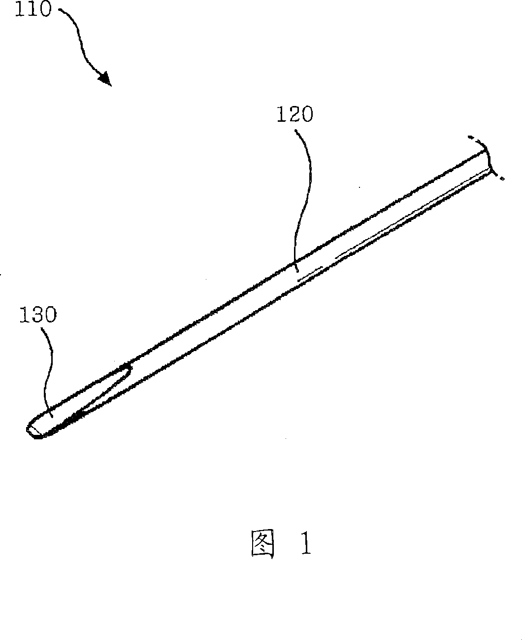
[0032] Fig. 1 is a perspective view of a medical needle according to a first embodiment of the present invention.

[0033] As shown in the figure, the medical needle 110 of the first embodiment of the present invention has a main body 120 having a circular cross-section extending to a predetermined length in which a top 130 is formed at a front end portion of the main body 120 .

[0034] Hereinafter, the part of each part of the medical needle 110 that is closest to the user (ie, the surgeon) is referred to as the proximal part, and the part of each part of the medical needle 110 that is farthest from the user is referred to as the distal part. end part.

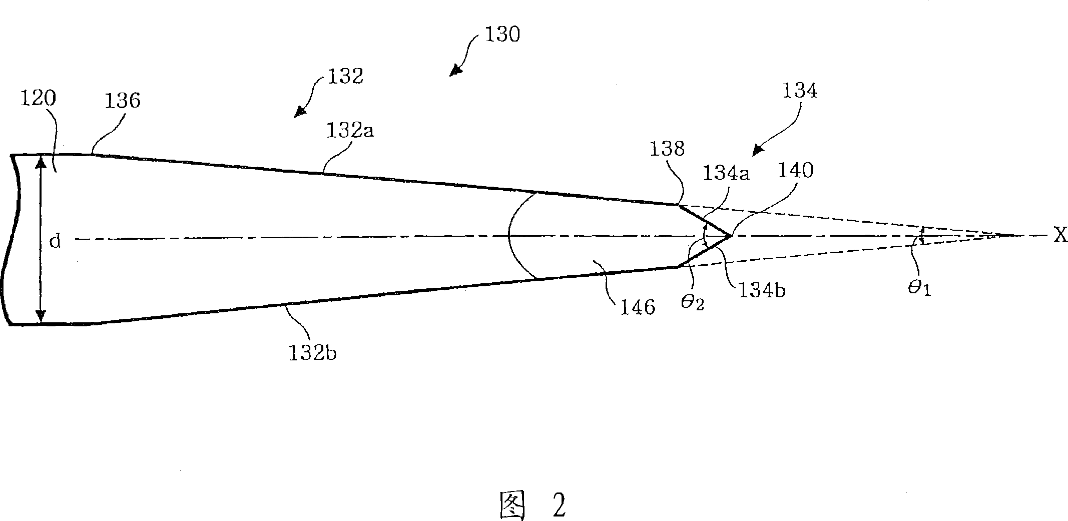
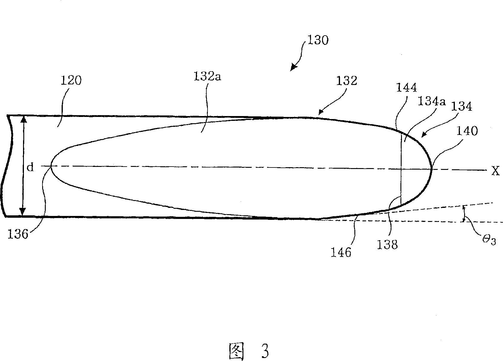
[0035] 2 and 3 are respectively a side view and a plan view of the medical needle shown in FIG. 1 .

[0036] As shown in these figures, the top 130 includes a first sloped region 132 and...


PUM


Abstract

A medical needle comprises a main body extending from a proximal end to a distal end, and a tip portion formed at the distal end of the body. The tip portion has a first inclined region, the cross-sectional area of which decreases toward the distal end and has a pair of surfaces inclined with an angle of 15 DEG to 20 DEG . The tip portion has a second inclined region extending from the first inclined region, the cross- sectional area of which decreases toward the distal end and has a pair of surfaces inclined with an angle of 30 DEG to 45 DEG . A tip is formed at the point of juncture of the pair of surfaces of the second inclined region. Tapered portions are formed on both sides of the first inclined region. Each tapered portion is inclined at an angle of 5 DEG to 15 DEG . Curved portions are formed at the points of juncture of the tip and the ta ered ortions.

Description

technical field [0001] The present invention relates generally to medical needles and, more particularly, to a medical needle for insertion into a patient's painful area or site for stimulation and / or injection therapy of certain painful or disabling areas or sites. Needle. Background technique [0002] Chronic pain has become a health problem that has grown dramatically in recent years. Studies to date have shown that stimulation therapy or injection therapy targeting painful areas or sites is one of the effective ways to manage or control chronic pain. [0003] US Patent No. 2,409,979 discloses a therapeutic needle for treating musculoskeletal pain, which will be described below with reference to FIGS. 9 and 10 . [0004] As shown in FIGS. 9 and 10 , such a needle comprises a body 10 of circular cross-section having a bore 11 terminating in a discharge end or outlet delimited by the edge of the wall of the body 10 . The body 10 is curved to have a curved surface 15 exte...

Claims


Application Information

Patent Timeline
29 Aug 2007
Publication
CN101027096A
IPC
A61M5/32
CPC
A61B17/3401; A61M5/3286; A61M2205/195; A61M5/32
Inventors
安刚