

Microporous ceramic filter
A technology of microporous ceramics and filters, applied in the field of filtration, can solve the problems of increased equipment cost, troublesome cleaning, and bulky equipment, and achieve the effects of long cleaning intervals, small flow resistance, and long life of filter elements
- Summary
- Abstract
- Description
- Claims
- Application Information
AI Technical Summary
Problems solved by technology
Method used
Image

Examples
Embodiment 1
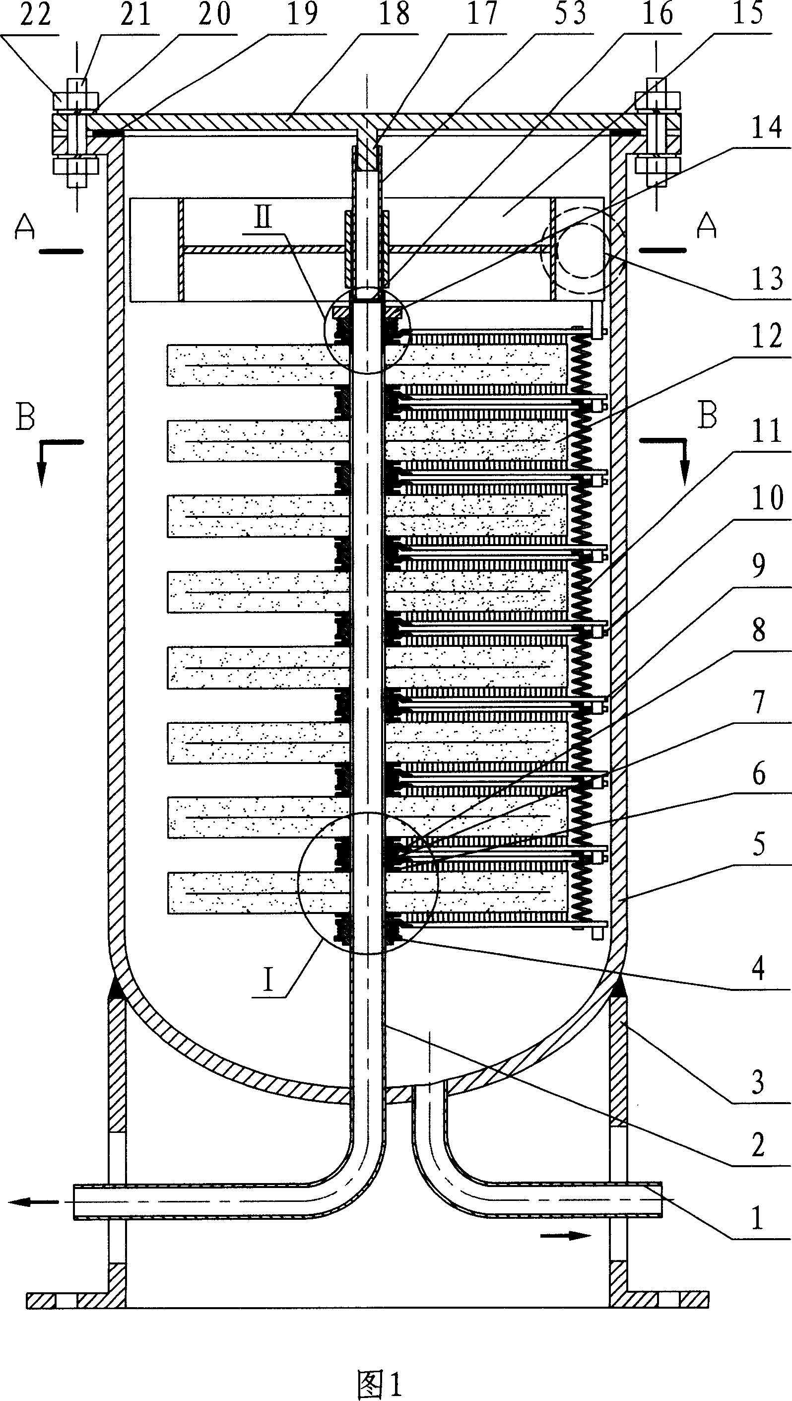
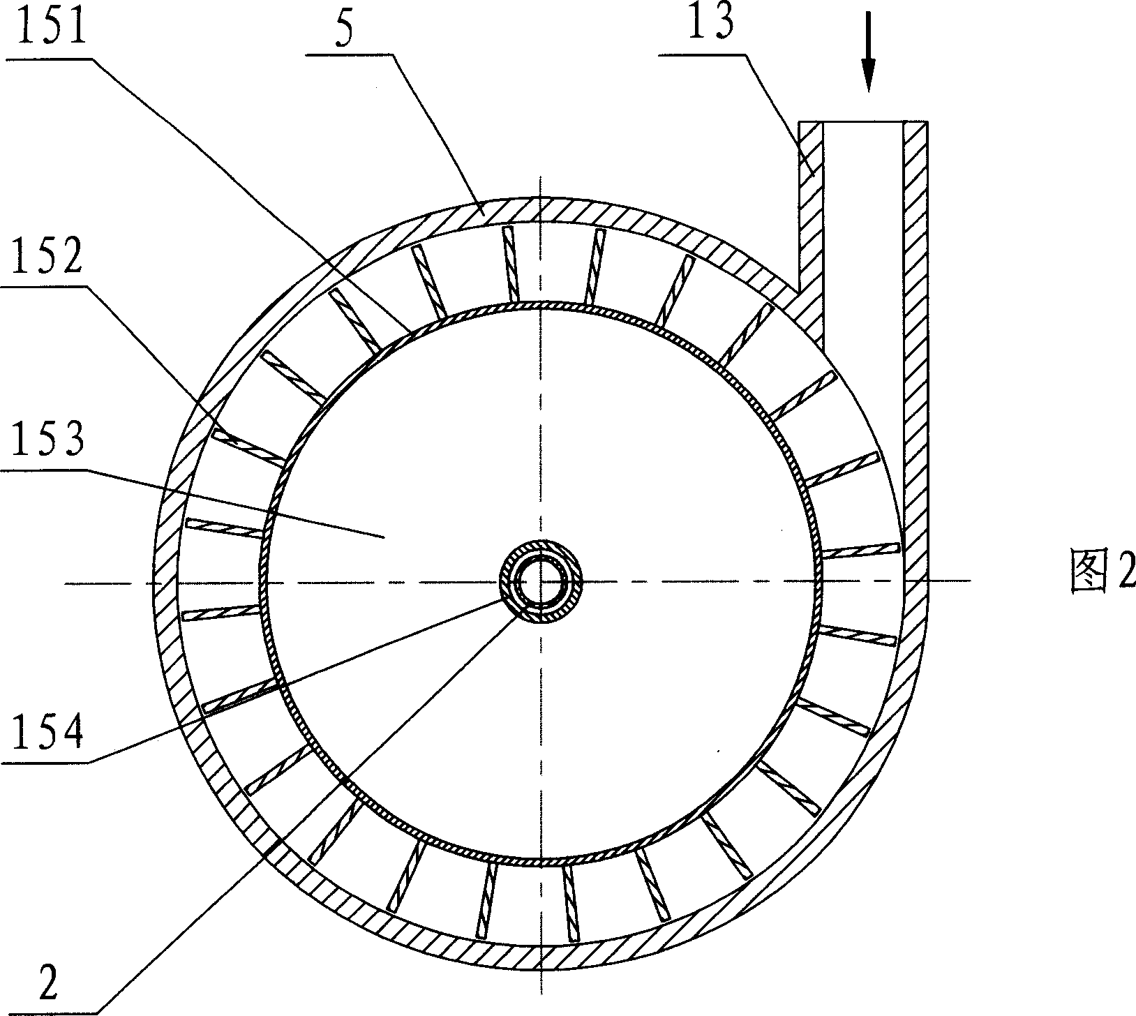
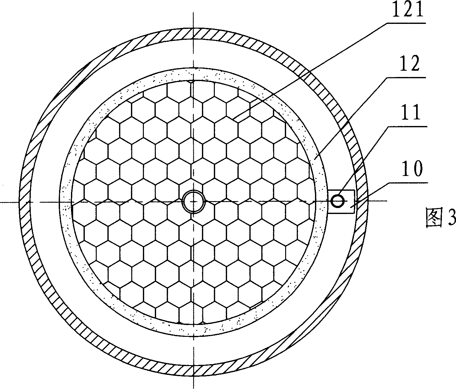
[0050] Embodiment 1: As shown in Fig. 1, Fig. 2, Fig. 3, Fig. 4, Fig. 5, Fig. 6, Fig. 7, Fig. 8, Fig. 9, the novel microporous ceramic filter of this embodiment includes a filter housing 5 and the combined microporous ceramic filter element in the shell 5. The microporous ceramic filter element is composed of multiple microporous ceramic sheets 12 that are filtered on both sides on the header 2. The outlet of the header 2 is the outlet of the filter. Each microporous ceramic sheet 12 is provided with a cleaning device, which rotates around the collector tube 2 through a transmission device, and cleans the trapped material on the surface of the microporous ceramic sheet 12 during rotation. The filter housing is also provided with an inlet pipe 13 and a sewage outlet pipe 1, the upper part of which is open, and an end cover 18 is provided at the open.
[0051] The collecting pipe 2 is a round pipe, one end of which is closed by a blind plate 16, and a short pipe 53 fixedly conne...
Embodiment 2
[0056] Embodiment 2: As shown in FIG. 10 , the transmission device of this embodiment is a transmission device powered by mechanical force, and its structure is to set an outer fixed shaft 26 and an inner fixed shaft at the inner and outer corresponding parts of the filter end cover 32 respectively. 28, the inner fixed shaft 28 is installed in the short tube 54 on the upper part of the header 2, the short tube 54 is fixedly connected with the header 2, and the outer turntable 23 and the inner turntable 52 are respectively sheathed on the two fixed shafts 26 and 28. Magnets 27 and 30 are mounted on the turntable, respectively. The outer turntable 23 is provided with a handle 29 on which a press cover 24 and a locking nut 25 are mounted, and are tightened and fixed by the locking nut 25 . A connecting rod 31 is also provided inside the filter. One end of the connecting rod 31 is provided with a rod 33 that can drive the cleaning device to rotate, and the other end is provided wi...
Embodiment 3
[0057] Embodiment 3: As shown in FIG. 11 , the transmission device of this embodiment is also a transmission device powered by mechanical force. 37 is provided with an annular groove on which the sealing ring 39 can be assembled at the fitting part with the shaft sleeve 41 , and the rotating shaft 37 and the shaft sleeve 41 are connected dynamically and sealingly through the sealing ring 39 . The rotating shaft 37 is provided with a rotating rod 38 which is fixed by a spring washer 36 and a nut 35 , and a handle 40 is mounted on the rotating rod 38 . There is also a connecting rod 42 inside the filter. One end of the connecting rod 42 is provided with a rod that can drive the cleaning device to rotate, and the other end is fixedly connected with the rotating shaft 37 . The external power is transmitted to the rotating shaft 37 through the handle 40 , and then to the cleaning device through the connecting rod 42 . The handle 40 and the rotating rod 38 can also be replaced by a...
PUM
 Abstract
Description
Claims
Application Information