Long-reach wavelength division multiplexing passive optical networks by using the position adjustment of broadband light source

A passive optical network and wavelength division multiplexing technology, applied in the field of WDM-PON, can solve the problems of difficult BLS, increased BLS cost, and difficult to control high-power BLS, etc., to reduce the initial installation cost and low installation investment cost. Effect

Active Publication Date: 2007-09-05
KOREA ADVANCED INST OF SCI & TECH
View PDF0 Cites 7 Cited by
  • Summary
  • Abstract
  • Description
  • Claims
  • Application Information

AI Technical Summary

Problems solved by technology

However, when the output power increases, there are some disadvantages that the cost for BLS increases rapidly and it becomes difficult to realize BLS
Also, it is not easy to control high power BLS

Method used


Image

  • Long-reach wavelength division multiplexing passive optical networks by using the position adjustment of broadband light source
  • Long-reach wavelength division multiplexing passive optical networks by using the position adjustment of broadband light source
  • Long-reach wavelength division multiplexing passive optical networks by using the position adjustment of broadband light source

Examples


Embodiment Construction

[0025] The structures and functions of the preferred embodiments according to the present invention will be described in more detail below with reference to the accompanying drawings.

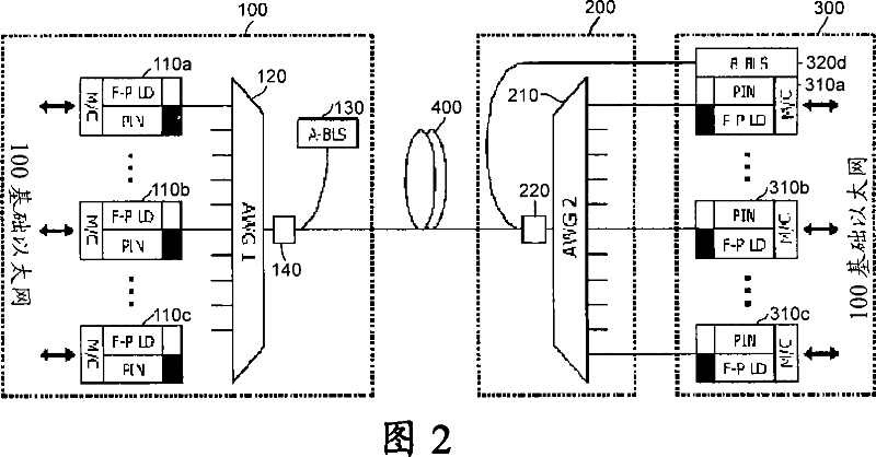
[0026] Fig. 2 shows a view of a WDM-PON for long-distance transmission in which the BLS is located at the user end according to the present invention. As shown in FIG. 2 , the WDM-PON for long-distance transmission with the BLS located at the ONT mainly includes a CO 100 , a remote node (RN) 200 , and multiple ONTs 300 .

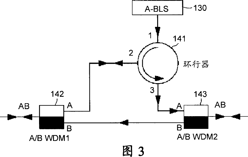
[0027] The CO 100 further includes: A-band BLS 130, to be incident into a light source for downstream signals; A-band BLS coupling device 140, for coupling A-band BLS; first wavelength division multiplexer / demultiplexer 120 , connected to the A-band BLS coupling device 140 for multiplexing / demultiplexing; Furthermore, a B-band BLS may be included in at least one neighboring CO for system protection purposes.

[0028] RN 200 includes: B-band BLS coupling device 220 for coupl...


PUM


Abstract

The present invention relates to a wavelength division multiplexing passive optical network (WDM-PON) for long-reach transmission using a position adjustment of a broadband light source (BLS), and particularly relates to a WDM-PON which extends s transmission distance of the WDM-PON by adjusting a position of a BLS so as to procure a high quality of service (QoS) and to reduce transmission costs in an optical network. A WDM-PON for long-reach transmission using a position adjustment of a broadband light source (BLS) in accordance with the present invention comprises a central office (CO) comprising an A-band BLS to be injected into a light source for downstream signals, an A-band BLS coupling device for coupling the A-band BLS, a first wavelength-division multiplexer / de not multiplexer connected to the A-band BLS coupling device for multiplexing / demultiplexing, and a plurality of first optical transceivers connected to the first wavelength-division multiplexer / d emultiplexer; a remote node (RN) comprising a B-band BLS coupling device and a second wavelength-division multiplexer / demultiplexer connected to the B-band BLS coupling device for multiplexing / demultiplexing, and being connected to the CO through an optical fiber; and a plurality of optical network terminations (ONTs) including a plurality of second optical transceivers connected to the second wavelength-division multiplexer / demultiplexer, wherein either the RN or one of the plurality of ONTs further includes a B-band BLS to be injected to a light source for upstream signals.An optical network system includes a central office (CO) comprising an A-band BLS to be injected into a light source for downstream signals, an A-band BLS coupling device for coupling the A-band BLS, a first wavelength-division multiplexer / demultiplexer connected to the A-band BLS coupling device for multiplexing / demultiplexing.

Description

technical field [0001] The present invention relates to a wavelength division multiplexed passive optical network (WDM-PON) for long-distance transmission using position adjustment of a broadband light source (BLS). More particularly, the present invention relates to a WDM-PON that extends the transmission distance of the WDM-PON to obtain high quality of service (QoS) and reduce transmission costs in an optical network by adjusting the location of a BLS. Background technique [0002] As the rapid growth of the Internet resulted in the evolution of voice and text-oriented services into video-based services, the need for wider bandwidth per user has also increased. To meet such demands, research on fiber-based passive optical networks (PONs) has been actively conducted. PON technology is divided into time division multiplexing passive optical network (TDM-PON) and WDM-PON. [0003] Usually, in PON, the maximum transmission distance between each user and the central office (...

Claims


Application Information

Patent Timeline
Patent Type & Authority Applications(China)
IPC IPC(8): H04B10/12H04B10/27H04B10/272H04J14/00H04J14/02
CPCH04J14/0246H04J14/0226H04J14/0282H04J14/02H04J14/025H04B10/25H04B10/2581
Inventor 李昌熹李相默金民桓
Owner KOREA ADVANCED INST OF SCI & TECH
Why Eureka
Try Eureka