

Vehicle drive
A driving device and vehicle technology, applied in the directions of power devices, electric power devices, electromechanical devices, etc., can solve the problems of difficulty in carrying vehicles and increase in the shape of drive components, and achieve the effect of easy installation and no increase in shape.
- Summary
- Abstract
- Description
- Claims
- Application Information
AI Technical Summary
Problems solved by technology
Method used
Image

Examples
no. 1 approach
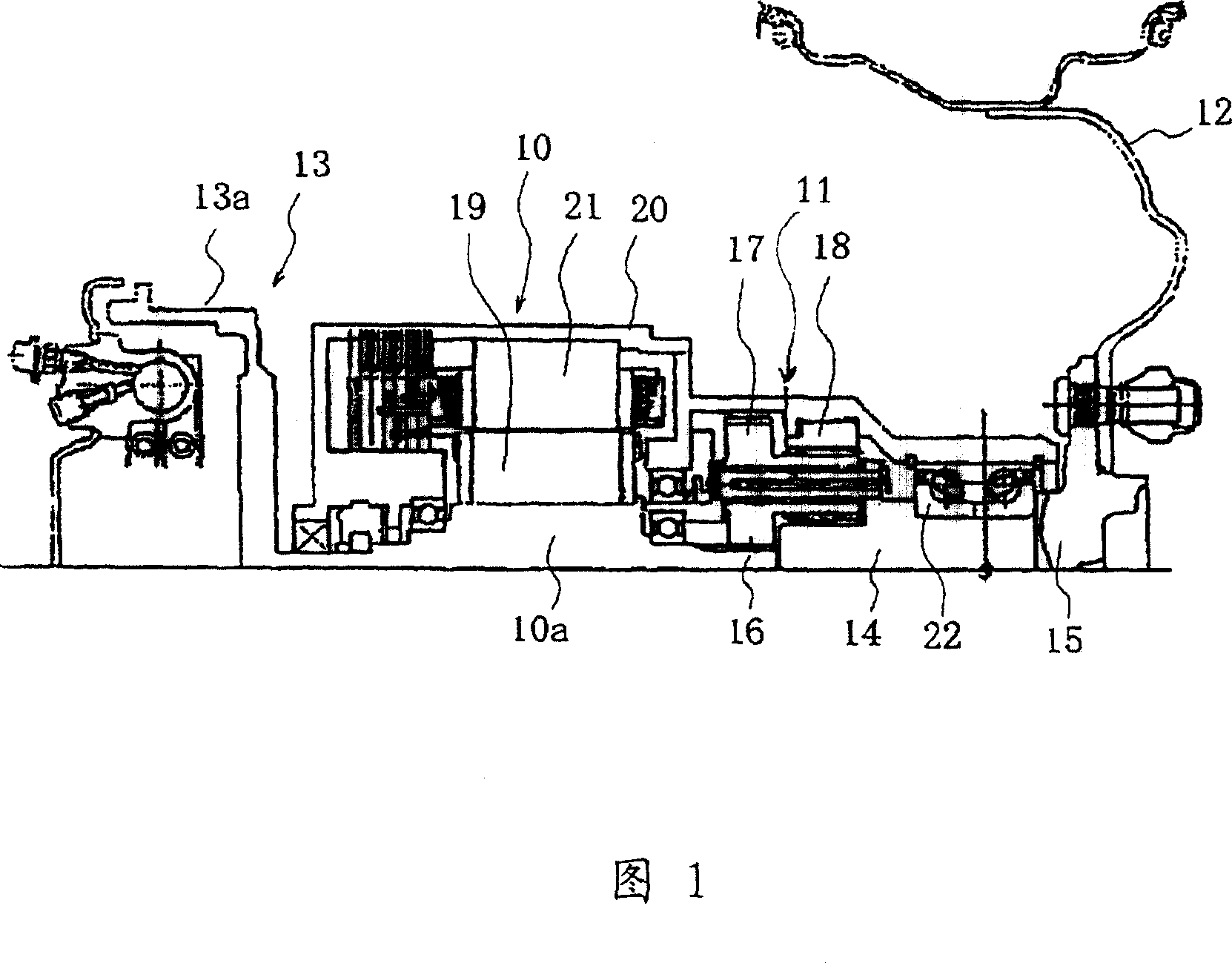
[0055] FIG. 1 is an explanatory cross-sectional view showing a driving device according to a first embodiment of the present invention. As shown in FIG. 1 , the in-wheel motor 10 together with the speed reducer constitutes a driving assembly to drive the wheel 12 . The in-wheel motor 10 and the speed reducer 11 are built in the wheel 12 together with the brake assembly 13 and the like. In this case, "installed inside" means that at least a part of the in-wheel motor 10 , the speed reducer 11 , and the brake assembly 13 are installed so as to enter the inner side of the wheel 12 .
[0056] The wheel 12 is attached to a hub 15 integrated with a carrier 14 which is an output shaft of the speed reducer 11 . The speed reducer 11 has a sun gear 16 , planetary gears 17 , a ring gear 18 , and a carrier 14 . The planetary gear 17 meshing with the sun gear 16 is meshed with the ring gear 18 and supports a rotation shaft on the carrier 14 so as to be rotatable. The sun gear 16 is provi...
no. 2 approach
[0069] 4 is an explanatory cross-sectional view showing a driving device according to a second embodiment of the present invention. As shown in FIG. 4, instead of the motor rotating shaft 10a, the in-wheel motor 40 is provided with a motor rotating shaft 41 integrally formed with a cup-shaped Rotary body 41b. The speed reducer 11 is arranged inside the cup-shaped rotating body 41b, and the speed reducer 11 is housed inside the in-wheel motor 40, and a casing 42 is formed that covers the in-wheel motor 40 as a whole in this state. Other structures and functions are the same as those of the driving device in Fig. 1 .
[0070] The in-wheel motor 40 has an inner wheel structure, and the driving force of the motor is transmitted from the motor rotating shaft 41 to the speed reducer 11 to rotate the planetary carrier 14 and rotate the wheel 12 mounted on the wheel hub 15 integrated with the planetary carrier 14. .
[0071] Thus, the cup-shaped rotating body 41 b has a shape exten...
no. 3 approach
[0082] 7 is a cross-sectional explanatory view showing a driving device according to a third embodiment of the present invention. As shown in FIG. 7 , the case 60 covers not only the entire in-wheel motor 40 disposed outside the cup-shaped rotating body 41b but also the entire brake drum 13a. Other structures and functions are the same as those of the driving device in Fig. 4 .
[0083] The case 60 covers the speed reducer 11 and the in-wheel motor 40 which are placed close to each other while overlapping the inner and outer peripheral portions of the case 60 , and also covers the brake drum 13 a in this state. That is, in the housings 42 , 48 , and 51 (see FIGS. 4 to 6 ) in the above-mentioned second embodiment, the brake drum 13 a exposed outside the housing is housed in the housing 60 together with the speed reducer 11 and the in-wheel motor 40 . Inside.
[0084] The in-wheel motor 40 has an inner wheel structure, and the driving force of the motor is transmitted from the...
PUM
 Abstract
Description
Claims
Application Information