Check patentability & draft patents in minutes with Patsnap Eureka AI!

Fuel ejection device and abnormity judgement method for the same

A fuel injection device and fuel injection technology, which are applied in the directions of fuel injection device, fuel injection control, charging system, etc., can solve problems such as difficult battery management, reduction of engine fuel supply, and control unit not working normally.

Active Publication Date: 2007-09-12
MITSUBISHI ELECTRIC CORP
View PDF2 Cites 5 Cited by
  • Summary
  • Abstract
  • Description
  • Claims
  • Application Information

AI Technical Summary

Problems solved by technology

[0009] If the battery is in a state of discharge and deterioration, the power necessary to drive the fuel injection module will not be obtained, and the amount of fuel supplied to the engine will be reduced, resulting in abnormal operating conditions of the engine
In addition, in the state of battery discharge and deterioration, sometimes the voltage of the battery decreases due to the drive of the fuel injection module, and the control unit that provides the drive signal to the fuel injection module will not work normally, and the engine cannot continue to run.
[0010] In the conventional fuel injection device disclosed in the above-mentioned patent document, there is a problem that the state of the battery cannot be accurately monitored because there is no device capable of properly judging the state of discharge and the state of deterioration of the battery.
Especially when used in small two-wheeled vehicles, due to the small power generation capacity of the generator and the small capacity of the battery, in order to avoid the above problems, it is necessary to strengthen the management of the battery, but it is difficult for ordinary users to carry out daily battery maintenance. manage

Method used


Image

  • Fuel ejection device and abnormity judgement method for the same
  • Fuel ejection device and abnormity judgement method for the same

Examples


Embodiment Construction

[0043] Embodiment 1

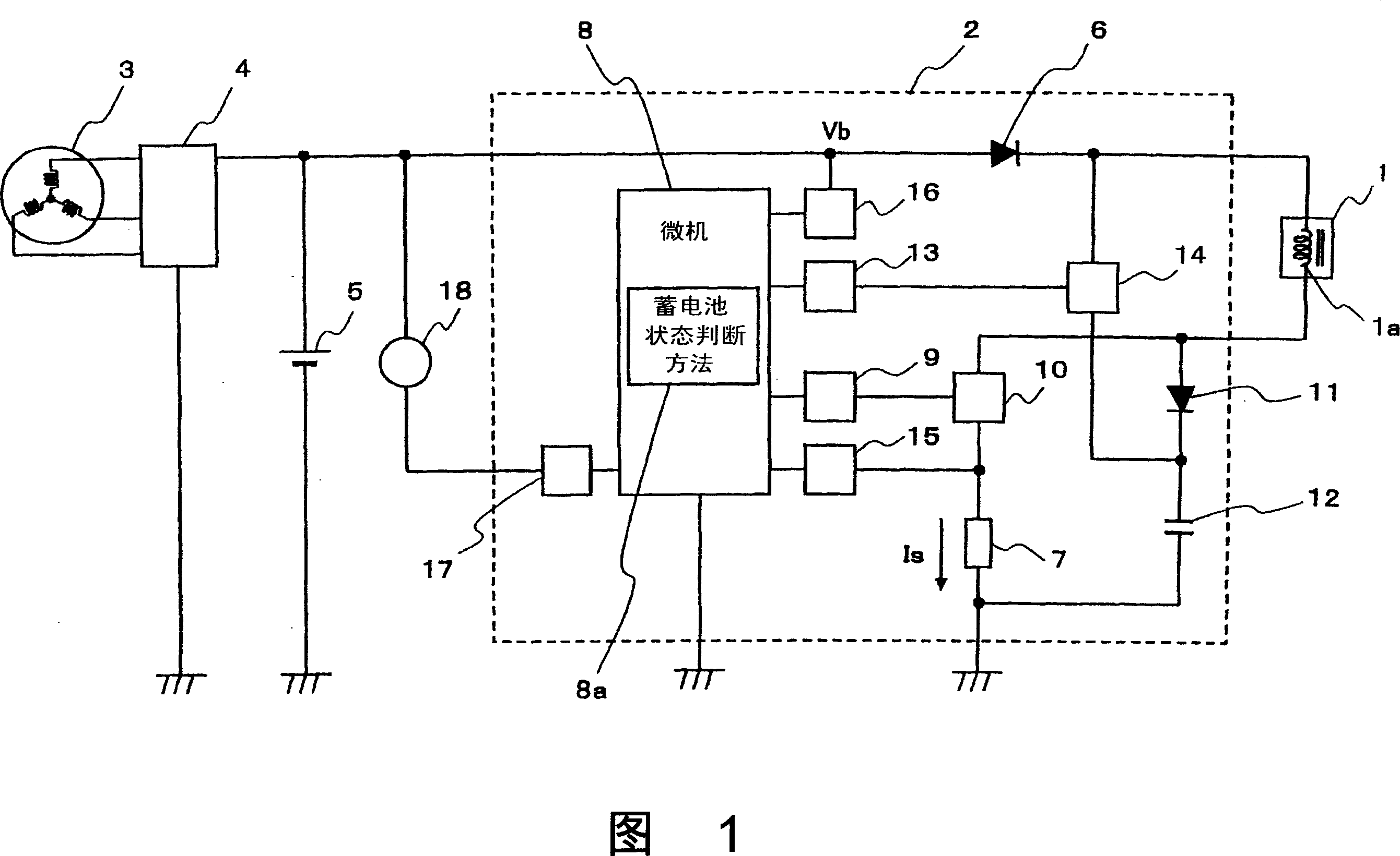
[0044]FIG. 1 is a block diagram of a fuel injection device according to the present invention. The fuel injection device includes a fuel injection module 1 with a plunger type electromagnetically driven pump that uses electromagnetic force as a driving source and pressure-feeds fuel introduced from a fuel tank (not shown in the figure); based on the operating state of the engine (not shown in the figure) A control unit 2 that gives drive signals to the fuel injection device; a generator 3 that is installed on the crankshaft of the engine and uses its rotation to generate electricity; a regulator 4 that optimally controls the generated voltage; and a storage battery 5 that stores the generated power.

[0045] The above-mentioned fuel injection module 1 has a solenoid coil 1a that electromagnetically drives the plunger (not shown in the figure), and one end of the solenoid coil 1a is connected to the battery 5 through a diode 6 for preventing backflow; The...


PUM


Abstract

A fuel jetting device can correctly detects the status of an accumulator, supervise the user to maintain the accumulator and prevent the circumstance that engine is abnormal and stop. The fuel jetting device includes a fuel jetting module (1) which has the function of making a plunger to do reciprocating movement by electrifying a solenoid 1a, sucking the fuel and pressing the fuel to jet; a control unit (2) for supplying drive signal to the fuel jetting module 1; a generator (3); and an accumulator (5). In the fuel jetting device, when the solenoid (1a) is conductive and it is at the conductive status for prescribed time, the accumulator voltage can be detected by an accumulator voltage detecting voltage circuit (16), the accumulator voltage is compared with a prescribed value by an accumulator status judge unit (8a) to judge the status of the accumulator, then the judge result is displayed on an accumulator status display lamp (18).

Description

technical field [0001] The present invention relates to a fuel injection device for an engine using a fuel injection module, and its abnormality judgment method. It is used, for example, in the fuel injection control of a two-wheeled vehicle engine, and the plunger is reciprocated by energizing the solenoid coil. , with the functions of inhaling fuel and pressurizing injection. Background technique [0002] In the electronically controlled fuel injection device in which the control unit calculates the fuel supply amount according to the engine speed and load, and provides a driving signal to the fuel injection valve, there is known a kind of using electromagnetic force to make the plunger reciprocate, suck fuel and then pressurize injection fuel injection module. This fuel injection module works in such a way that the solenoid coil is energized according to the drive signal given by the control unit, and the plunger pressurizes the fuel to inject it at a prescribed fuel pre...

Claims


Application Information

Patent Timeline
Patent Type & Authority Applications(China)
IPC IPC(8): F02D41/20F02M51/00F02M57/02
CPCY02T10/40
Inventor 松野平笃志和田修一入江太津治山川智也
Owner MITSUBISHI ELECTRIC CORP
Features
  • R&D
  • Intellectual Property
  • Life Sciences
  • Materials
  • Tech Scout
  • Unparalleled Data Quality
  • Higher Quality Content
  • 60% Fewer Hallucinations
Learn More