
Wind-power pumping water generating system

A power generation system and hydroelectric generator technology, applied in wind power generation, hydropower generation, wind power generators, etc., can solve problems such as high investment costs, low utilization efficiency of wind turbines, and poor power quality

Inactive Publication Date: 2007-09-12
INST OF ELECTRICAL ENG CHINESE ACAD OF SCI
View PDF2 Cites 50 Cited by
  • Summary
  • Abstract
  • Description
  • Claims
  • Application Information

AI Technical Summary

Problems solved by technology

[0007] In Example 1 of patent 01135136.5 "Feng Shui Combined Power Generation Method and Device", the wind energy is firstly converted into electrical energy through the wind generator, and then the electric energy is used to drive the electric water pump to pump water. In this process, complex rectification equipment is still required to convert the output of the wind generator The electric energy is converted into the electric energy required by the electric water pump, the input cost is high, and the power quality is poor
In Embodiment 2, one wind wheel is equipped with one waterwheel or water lifter, which is suitable for small-scale wind-shui power station projects, and the utilization efficiency of large-scale wind turbines is low
[0008] Patent 200610026128.0 "A Method of Wind-Hydraulic Combined Power Generation" describes that water is lifted from a low place to a high place through wind-powered water lifting equipment. For large-scale wind turbines, the distance from the ground is tens of meters or even hundreds of meters, which will lose the power of the wind turbine and The potential energy of the high water surface difference will greatly reduce the conversion efficiency of wind energy

Method used


Image

  • Wind-power pumping water generating system

Examples


Embodiment Construction

[0017] The present invention will be further described below in conjunction with the accompanying drawings and specific embodiments.

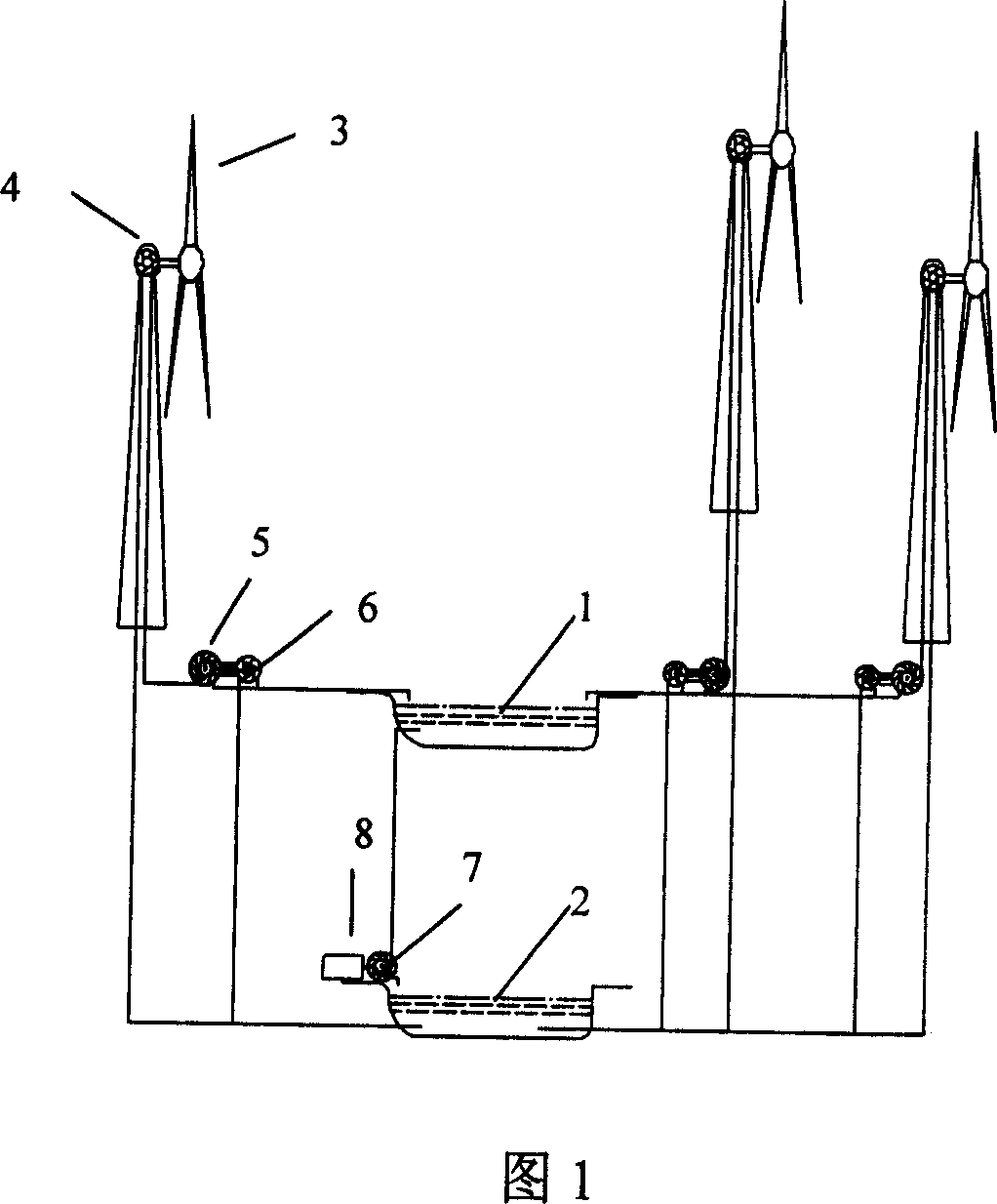
[0018] As shown in the drawings, the low-level reservoir 2 is located at the lowest point, and the high-level reservoir 1 is higher than the low-level reservoir 2 . The hydraulic turbine 7 and the hydraulic generator 8 are located between the high-level reservoir 1 and the low-level reservoir 2 in vertical height. The water turbine 7 and the water turbine generator 8 are coaxially connected. The fan 3 and the water pump 4 are coaxially connected and are higher than the high-level reservoir 1 . The water turbine 5 and the water pump 6 are coaxially connected and located between the water pump 4 and the high-level reservoir 1 . The height of the reservoir is calculated by the height of the water surface.

[0019] The blower fan 3 rotates under the effect of wind force, drives the water pump 4 to pump the water in the low-level reservoir 2 into...


PUM


Abstract

A wind pumping generating system contains high reservoir (1), low reservoir (2), fan (3), water pump (4, 6), water turbine (5, 7) and hydraulic generator (8). The fan rotates under the wind action to drive (4) pump water from (2). The water flows into (5) through pipe to drive it rotating. The effluent water from (5) will flow into the (1). Rotation of (5) drives (6) working, which pumps water in (2) into (1) through pipe. Water from (1) washes (7) and drives it rotating. Water from (7) will flow into (2). Rotation of (7) drives (8) rotating for generating electricity. The invention has high wind usage, small investment, low cost and output electric energy with high quality.

Description

technical field [0001] The invention relates to the field of wind power utilization, in particular to wind power water extraction and hydropower generation. Background technique [0002] The utilization of wind energy mainly adopts the mode of generating electricity by wind power generator at present, and also has a small amount of ways of raising water by wind power for irrigation and drinking water. [0003] Wind turbine power generation is the wind energy driving the rotation of the fan, which drives the generator to generate electricity. Due to the great uncertainty of the wind energy, the running speed of the wind turbine is very unstable, and the voltage, waveform, and frequency of the electric energy generated by the generator are difficult to meet the requirements of grid connection. It is usually rectified by a rectifier circuit, and can only be input into the grid after meeting the requirements of grid connection. The device for rectifying the electric energy out...

Claims


Application Information

Patent Timeline
Patent Type & Authority Applications(China)
IPC IPC(8): F03D9/00F04D13/04F03B13/06F03D9/14F03D9/28
CPCY02E60/17Y02E10/72Y02E10/22Y02E10/20Y02E60/16Y02E70/30Y02P80/10
Inventor 熊斌宋福川田新东顾国彪常振炎
Owner INST OF ELECTRICAL ENG CHINESE ACAD OF SCI
Learn More