Clutch mechanism having cushioning function

A clutch mechanism and function technology, applied in the direction of intermeshing clutches, clutches, mechanical drive clutches, etc., can solve problems such as efficiency, high cost, and complex components that do not meet industrial demands and economic demands, and achieve guarantees Safe and long service life, injury prevention, compact structure

Inactive Publication Date: 2007-09-12
刘仁炽
View PDF1 Cites 17 Cited by
  • Summary
  • Abstract
  • Description
  • Claims
  • Application Information

AI Technical Summary

Problems solved by technology

[0004] In these designs, when the displacement of the shifting fork sleeve bridges the two rotating shafts to generate a power transmission connection, the displacement of the shifting fork sleeve on one rotating shaft intends to engage and the other rotating shaft is instantly meshed and misaligned. Due to the design technology and space type factors, the components are complicated and occupy space, so the external space of the machine tool is used to set up the relevant buffer mechanism separately. Not only the structure is complex, the volume is large, the cost is high, but also the assembly process is time-consuming and labor-intensive. , does not meet the utilization of industrial demands and the efficiency of economic demands

Method used


Image

  • Clutch mechanism having cushioning function
  • Clutch mechanism having cushioning function
  • Clutch mechanism having cushioning function

Examples


Embodiment Construction

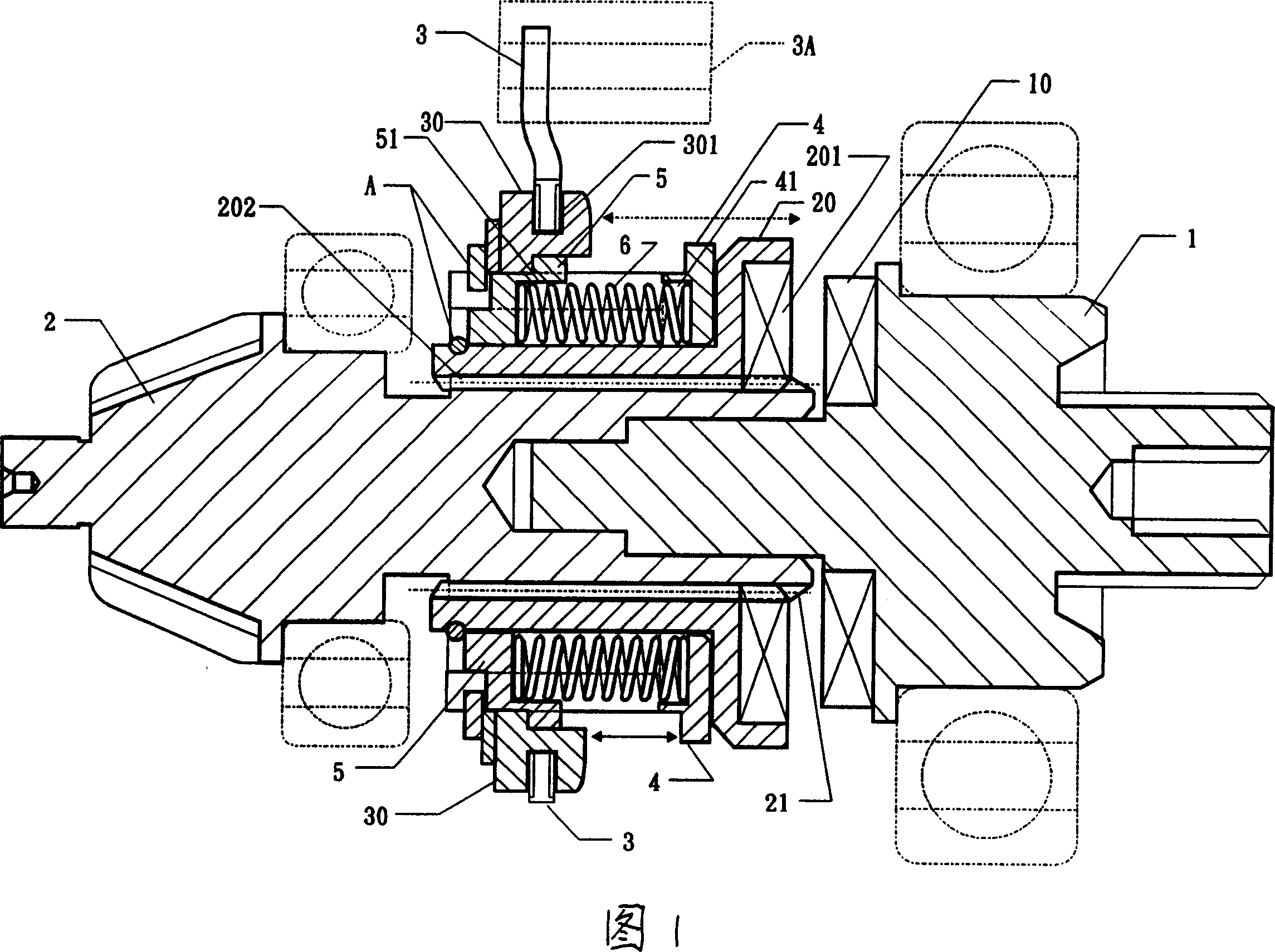
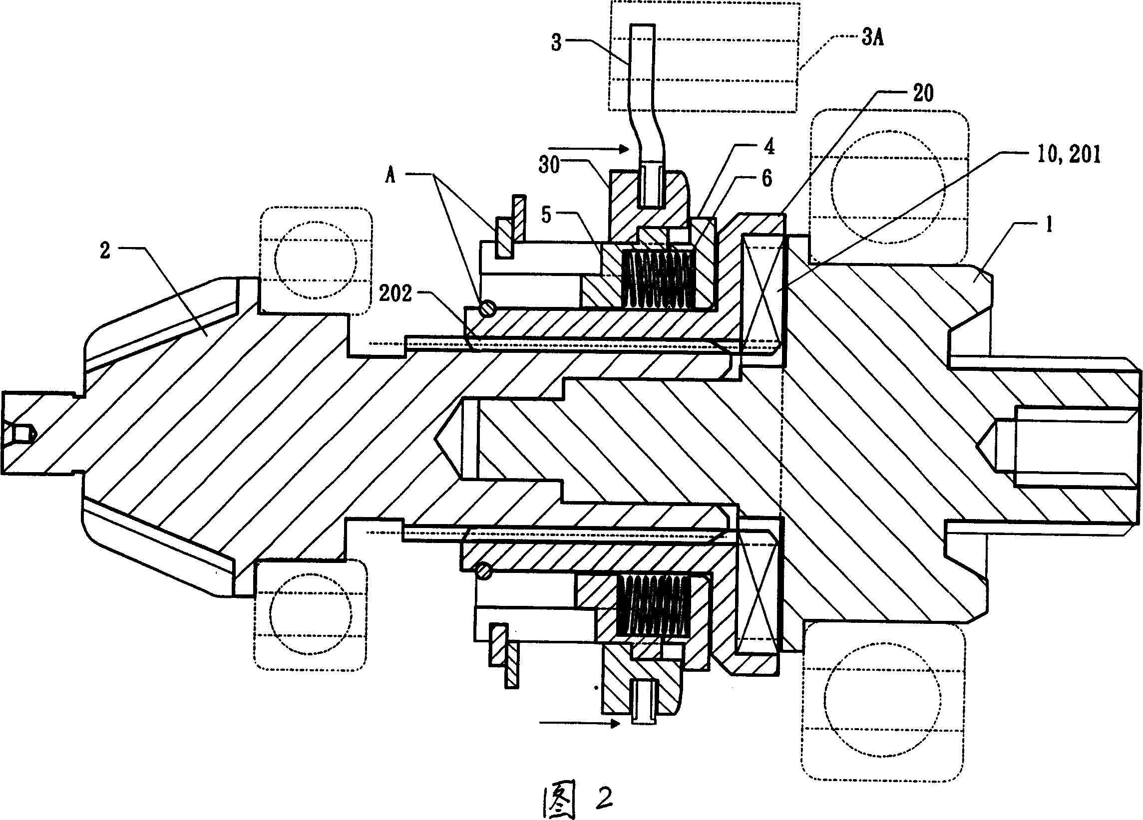
[0044] First referring to the accompanying drawings, Fig. 1 and Fig. 2 are all schematic diagrams of an embodiment of a clutch mechanism with a buffer function in the present invention, the first mandrel 1 of the clutch mechanism is fixedly provided with an engaging tooth surface 10, and the front section shaft of the second mandrel 2 The body is provided with a rack 21 for positioning and meshing and can be axially displaced on the setting of the clutch sleeve 20 on the shaft rod of the second mandrel 2. The front end of the clutch sleeve 20 is provided with an engaging tooth surface 201, and the shaft hole of the sleeve is There is a tooth groove 202 that can be engaged and positioned and axially displaced, and the clutch sleeve 20 on the shaft of the second spindle 2 is linked by a clutch collar 30 that can be axially displaced by the control of the shift fork 3. A buffer mechanism is provided between the clutch collar 30 and the clutch sleeve 20. The buffer mechanism includ...


PUM


Abstract

The invention discloses a clutch mechanism with buffer. It contains a fist spindle, a secondary spindle and a clutch sleeve with location meshing which can move along radial on axostyle of the secondary spindle. Set a meshing face on end of the first spindle and a gear rack on front section of the secondary spindle. The clutch sleeve is coupled by a clutch collar controlled by a shifter which can move along radial and a buffer mechanism is set between them. The buffer mechanism contains a spring sleeve, a buffer ring and a spring between them. The invention has simple structure, low cost, small capacity and easy equipment, which can effectively avoid damages on driving module caused by dislocation of active gear and passive gear and guarantee safe and long useful life of machine.

Description

technical field [0001] The invention relates to a clutch mechanism with a buffer function that can be widely used in shaft transmission. Background technique [0002] Generally, the design of the clutch mechanism for the shaft transmission of the vehicle is known, such as: US Patent No. 5,997,428 related to the power switching clutch design of the two-wheel transmission and the four-wheel transmission. [0003] The previous technical literature discloses a clutch design mechanism for power transmission between two rotating shafts, which uses a shift fork sleeve disposed between opposite ends of the two rotating shafts to generate a clutch for power transmission between the two rotating shafts. [0004] In these designs, when the displacement of the shifting fork sleeve bridges the two rotating shafts to generate a power transmission connection, the displacement of the shifting fork sleeve on one rotating shaft intends to engage and the other rotating shaft is instantly meshe...

Claims


Application Information

Patent Timeline
Patent Type & Authority Applications(China)
IPC IPC(8): F16D23/12F16D11/00F16H37/02
Inventor 刘仁炽
Owner 刘仁炽
Why Eureka
Try Eureka