Straight-through current transformer for taking voltage from wrapping conductor using puncturing method

A current transformer and core-through technology, applied in the field of transformers, can solve the problems of easy electricity theft and low efficiency, and achieve the effect of avoiding electricity theft, easy to use, and realizing the anti-theft function

Inactive Publication Date: 2007-09-12
HUBEI SHENGJIA ELECTRIC EQUIP
View PDF0 Cites 8 Cited by
  • Summary
  • Abstract
  • Description
  • Claims
  • Application Information

AI Technical Summary

Problems solved by technology

[0003] Aiming at the problems of complex operation, low efficiency, easy electricity stealing and large space occupation in the current method of peeling and obtaining voltage, the present invention provides a current transformer, which can conveniently obtain voltage by innovatively designing the structure of the current transformer signal, and it perfectly solves the problem of easy power theft and low efficiency in the current way of taking voltage

Method used


Image

  • Straight-through current transformer for taking voltage from wrapping conductor using puncturing method
  • Straight-through current transformer for taking voltage from wrapping conductor using puncturing method
  • Straight-through current transformer for taking voltage from wrapping conductor using puncturing method

Examples


Embodiment 1

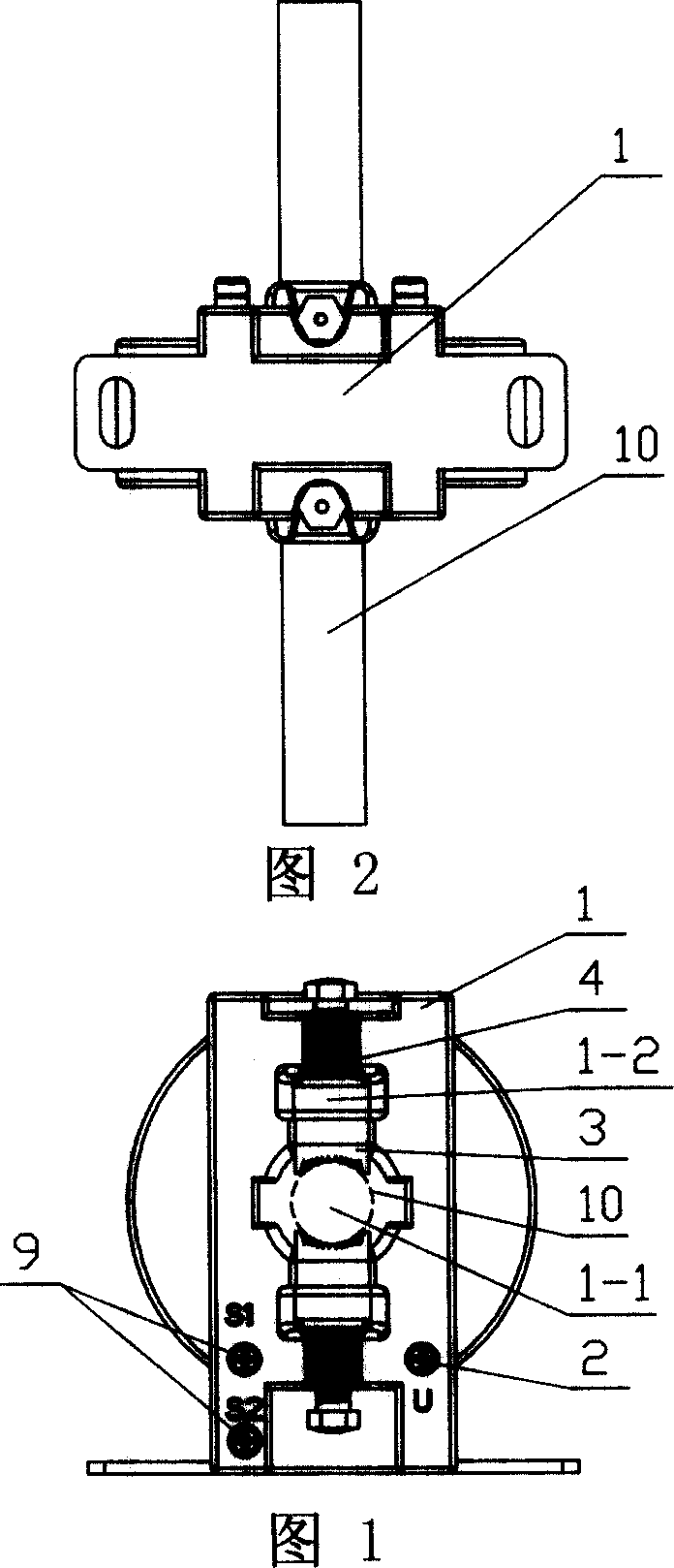
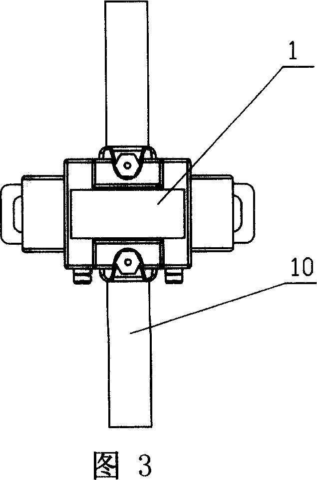
[0040] A core-through current transformer that uses a puncture method to take voltage from the sheathed wire, referring to Figures 1 to 5, it includes a transformer body 1, and the transformer body 1 is respectively provided with a voltage line outlet terminal 2 and a voltage-taking component 3. The voltage line outlet terminal 2 and the voltage-taking component 3 have a connection relationship, and this connection relationship includes any connection in the prior art. For example, Baoding Kaiyu Electric Co., Ltd. has produced a LDF1-0.66 guide rod penetrating type current transformer, which casts the connecting wire between the voltage line outlet terminal 2 and the voltage-taking component 3 together in the transformer housing; the same thing as this embodiment is that it sets three on the transformer The outlet terminals are two current wire outlet terminals 9 and one voltage wire outlet terminal 2; the difference from this embodiment is that the voltage taking part 3 in thi...

Embodiment 2

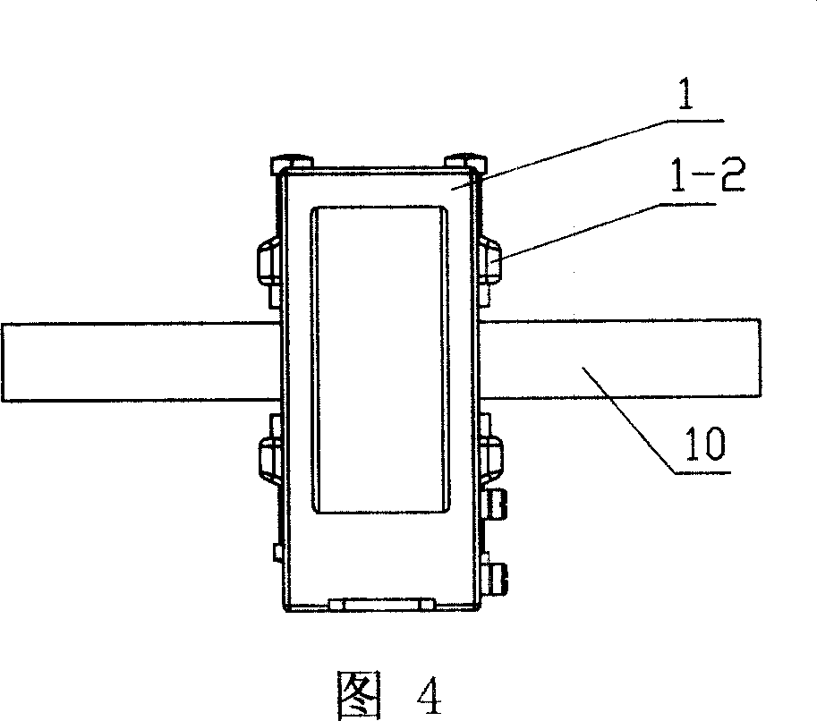
[0048] For the situation where the voltage is taken through the metal stud 4 as a conductor, a more preferred structure is that on the transformer body 1, two metal inserts 1-2 are set around the through-hole 1-1, referring to Figure 7, all The metal inserts 1-2 are electrically connected through a conductor 15. Referring to FIG. 8, the conductor 15 in this embodiment is a metal sheet, and of course a wire can also be used for electrical connection. All metal inserts 1-2 are threaded with studs 4, and like this, the voltage-taking parts in two directions pierce the tips into the bus bar at the same time, so that the electrical connection is more stable and accurate, so that the voltage on the bus bar can be better connected The signal is passed on.

[0049] It is conceivable that in practical applications, the studs are not limited to the two mentioned above, and may also be three, four, or more, and the fixing method between the studs and the transformer is not limited to fix...

Embodiment 3

[0053] The difference from the existing structure is that the No. 1 anti-stealing mask 5 described in this embodiment is connected to the surface of the transformer body 1 in a non-detachable manner. It can be seen that the anti-stealing mask defined in this embodiment is fixed. On the body of the transformer, in this way, the transformer can be used in any position and not limited to the box. The mask is connected to the transformer body in a non-detachable way, that is to say, after the metering department fixes the anti-stealing mask to the transformer, the mask cannot be removed from the transformer without destroying it. Those who can't hide the eyes and ears to steal electricity can greatly increase the degree of protection against electricity theft.

[0054] Referring to Figures 9 to 11, this non-detachable connection structure is that the No. 1 anti-stealing mask 5 located on one side of the transformer is a whole, and the No. 1 anti-stealing mask 5 is provided with a ...


PUM


Abstract

This invention relates to a straight-through current transformer using puncture method to taking voltage form wrapping wire. The invention includes transformer noumenon(1). On the transformer noumenon (1) the invention set voltage-wire leading-out terminal (2) and voltage taking assembly (3) that has connected relation. the voltage taking assembly(3) possess spinal leading end, can puncture insulation skin of generatrix then touch metal core, thereby realize purpose of taking voltage. The structure of current transformer is simplicity; space taking up is smallness, cost low, and voltage taking mode shortcut. The invention could hugely advance work efficiency, at the same time, the connecting between voltage taking assembly and generatrix is stable.

Description

technical field [0001] The invention relates to a transformer. Background technique [0002] In many feed-through current transformers currently used, there is no voltage signal output, and the voltage signal must be obtained from the exposed busbar. For the busbar with insulation, the voltage needs to be obtained by peeling off the busbar insulation. This method of obtaining voltage has the disadvantages of complicated operation and low efficiency, and electricity thieves often take the method of removing or cutting the wires so that the voltage signal cannot enter the energy meter. The connection point of the busbar, or inserting insulating objects at the junction of the connection point and the busbar, etc., can reduce the voltage metering to achieve electricity stealing. In addition, electricity stealers also use loads connected in series before the connection point to realize electricity stealing and control voltage. Therefore, in practical applications, in order to pr...

Claims


Application Information

Patent Timeline
Patent Type & Authority Applications(China)
IPC IPC(8): G01R15/18
Inventor 万家盛
Owner HUBEI SHENGJIA ELECTRIC EQUIP
Why Eureka
Try Eureka