Apparatus for monitoring a state of an electrical switching device

A technology for electrical switches and switchgear, applied in the direction of switchgear status indication, electric switches, components of protective switches, etc.

Inactive Publication Date: 2007-09-12
SIEMENS AG
View PDF1 Cites 8 Cited by
  • Summary
  • Abstract
  • Description
  • Claims
  • Application Information

AI Technical Summary

Problems solved by technology

In addition, the pivot bearing of the status indicator is subject to high wear under normal switching
There is thus a contradiction between a smooth setting of the status indicator for effort-saving movement and a reliable, durable support of the status indicator

Method used


Image

  • Apparatus for monitoring a state of an electrical switching device
  • Apparatus for monitoring a state of an electrical switching device
  • Apparatus for monitoring a state of an electrical switching device

Examples


Embodiment Construction

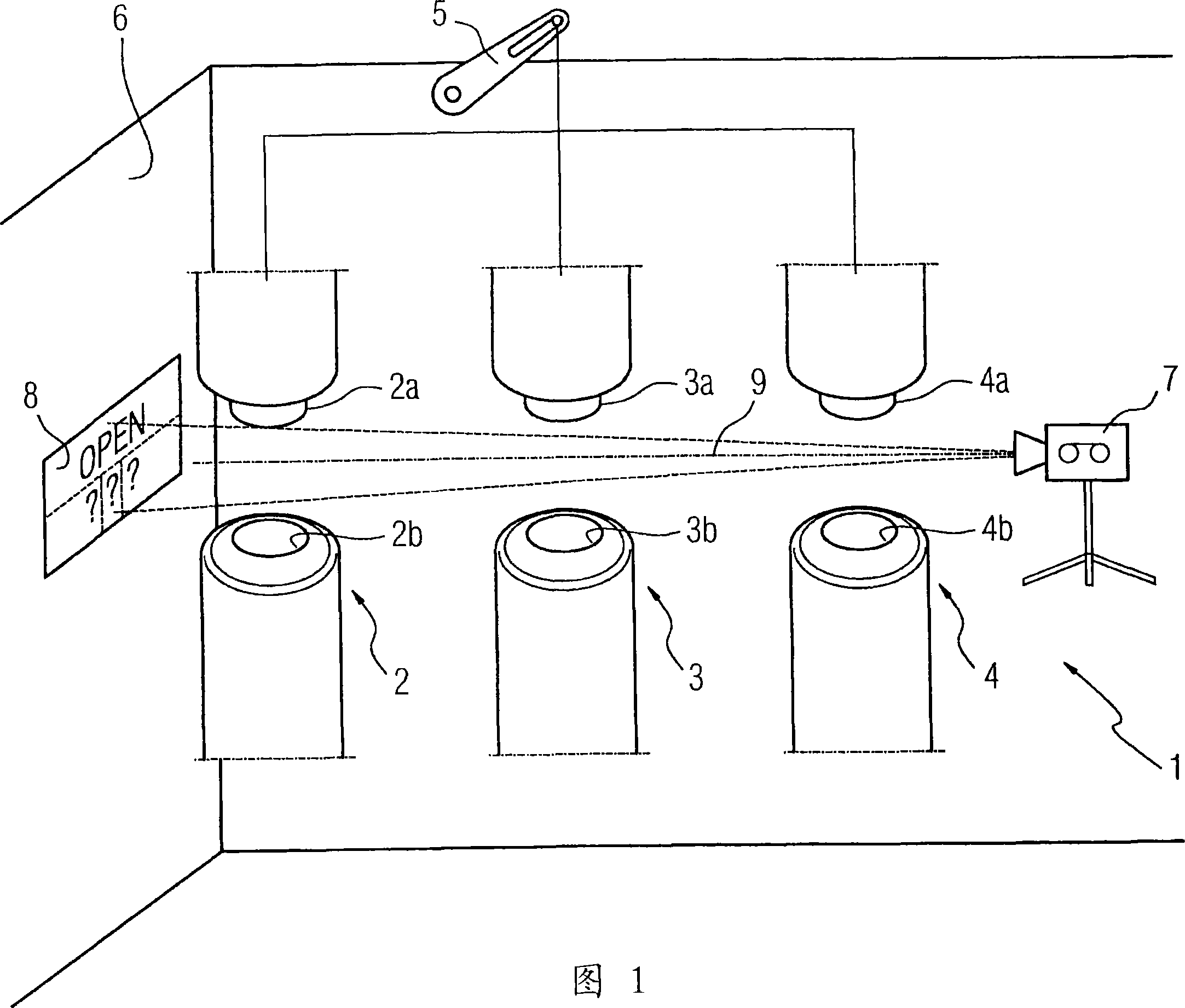
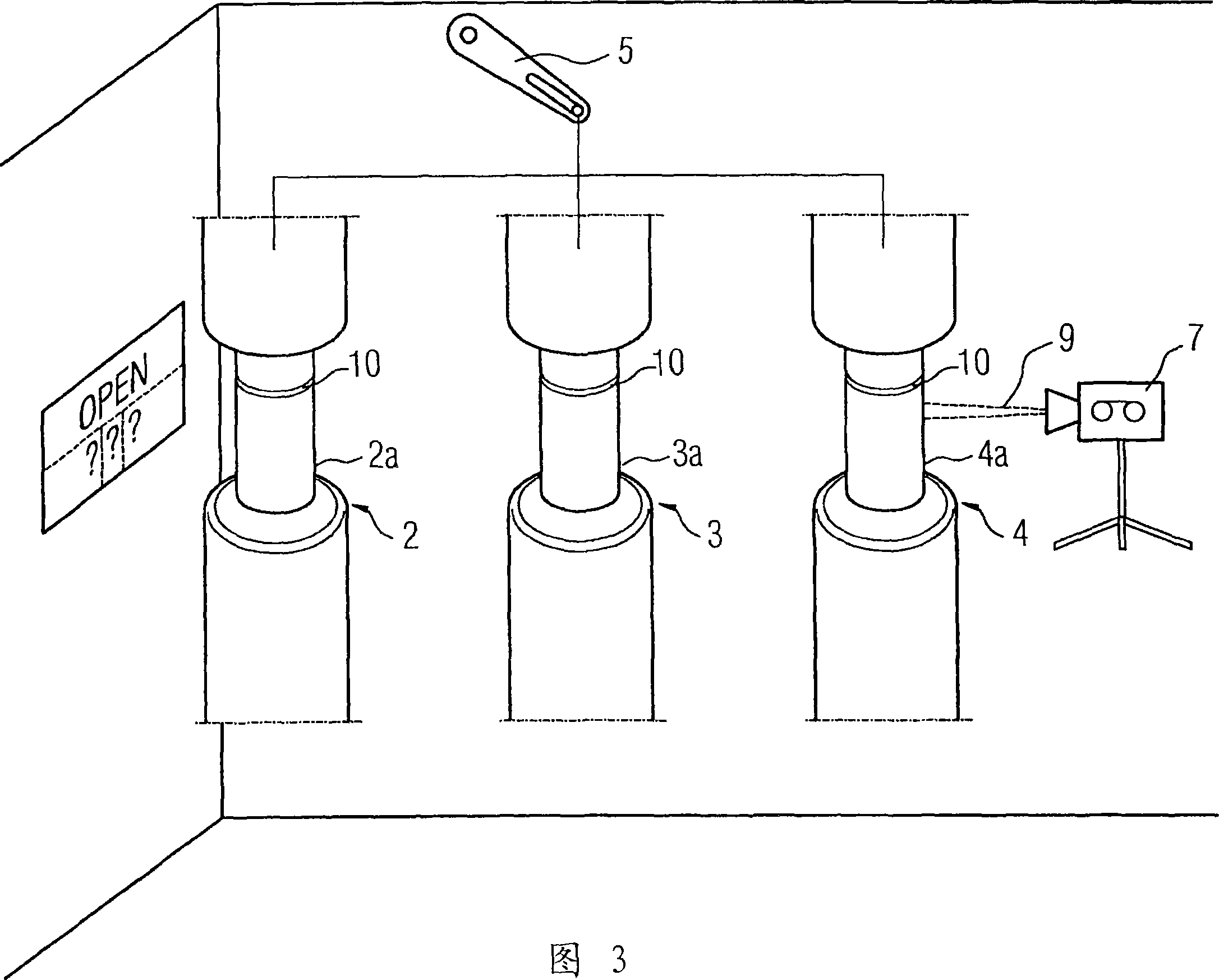
[0031] An electrical switching device 1 is shown in the figure. The electrical switching device 1 has first, second and third switching contacts 2 , 3 , 4 . The first switching contact 2 has a first movable switching contact 2 a and a first counter contact 2 b. Likewise, the second and third switching contacts 3, 4 each have a movable switching contact 3a, 4a and a fixed counter contact 3b, 4b. The movable contacts 2a, 3a, 4a are configured in the shape of pins. The opposite contacts 2b, 3b, 4b are designed to be tubular. The movable switching contact 2a, 3a, 4a enters the tubular counter-contact 2b, 3b, 4b during the switching process. The movable switching contacts 2 a , 3 a , 4 a can be moved by a kinematic chain with a pivotable lever 5 . The pivotable lever 5 can be deflected eg by means of an electromagnetic drive or a stored energy spring drive. The switching device 1 is arranged in an encapsulation housing 6 . The encapsulating housing 6 is designed as a compress...


PUM


Abstract

Disclosed is an electrical switching device (1) comprising a state indicator (8) which is covered or uncovered in accordance with the state of the switching device (1). In order to reduce the amount of moved masses, the state indicator (8) remains in a resting position during a switching process of the electrical switching device (1). The state indicator (8) can be covered at least in part by the movable switching contact pieces (2a, 3a, 4a) of the electrical switching device (1), for example.

Description

technical field [0001] The invention relates to a device for monitoring the status of an electrical switching device with a status indicator which is covered or uncovered depending on the status of the switching device. Background technique [0002] Such a device is known, for example, from German publication DE 19955588 A1. The known switching device is designed as a power switch and comprises a housing, a network connection, and a load connection. Switchable contacts are provided between the grid connection and the load connection. When activating the electrical switching device, a so-called triggering cam acts and opens the switchable contacts of the known electrical switching device. A status indicator is provided so that the switching state of the switching device can be seen from the outside. The status indicator is designed in the form of a deflectable pendulum. Such a rocker is deflected depending on the switching state of the known switching device and can eithe...

Claims


Application Information

Patent Timeline
Patent Type & Authority Applications(China)
IPC IPC(8): H01H9/16
CPCH01H71/04H01H2001/0021H01H1/0015H01H2071/048H01H9/168
Inventor 沃杰西奇·奥尔泽斯基彼得·施密特
Owner SIEMENS AG
Why Eureka
Try Eureka