

Optical disk and optical disk apparatus
A technology for optical discs and equipment, which is applied in the directions of optical record carriers, optical record carrier manufacturing, recording/reproducing by optical methods, etc., and can solve the problems of shortened service life of the recording layer and decreased reliability.
- Summary
- Abstract
- Description
- Claims
- Application Information
AI Technical Summary
Problems solved by technology
Method used
Image

Examples
no. 1 example
[0052] structure and material
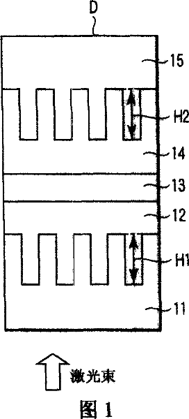
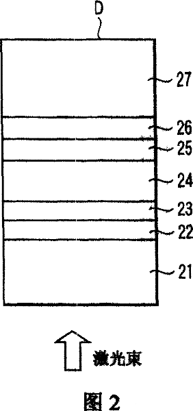
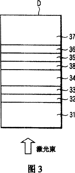
[0053]FIG. 1 is a cross-sectional view showing an example of dimensions of grooves in a dual-layer recordable optical disc according to an embodiment of the present invention. Fig. 2 is a cross-sectional view showing an example of its layer structure. Fig. 3 is a cross-sectional view showing an example of its layer structure. FIG. 1 shows only substrates, and FIG. 2 shows a state where an information recording layer is formed on the substrates and the substrates are adhered to each other.
[0054] As shown in Figure 1, in the optical disc D according to the present invention, the transparent substrate 11, the first information layer 12, the adhesive layer (intermediate layer) 13, the second information layer 14, and the substrate 15 are viewed from the incident laser beam plane. Arrange in the above order. A polycarbonate (PC) substrate or a glass substrate can be used as the substrate 11 or 15 . In the substrate or the adhesive layer, a gro...
no. 2 example
[0086] The second embodiment illustrates that the grooves of the first information layer 22 are provided in the transparent substrate 71 and the grooves of the second information layer 74 are provided in the substrate 75 . Here, no grooves are provided in the adhesive layer 73 .
[0087] More specifically, as shown in FIG. 13, the grooves provided in the first information layer 12 and the second information layer 14 in FIG. 1 are formed in the transparent substrate 71 and the substrate 75, respectively. In this example, the above-mentioned first to third test data and the recording and reproduction characteristics of Comparative Examples 1 and 2 were obtained.
[0088] Also, with respect to the grooves formed in the first and second information layers, recording can be performed only on grooves close to the laser beam incident face. Also, with regard to the grooves formed in the first and second information layers, recording can be performed only on grooves far from the laser...
no. 3 example
[0090] The third embodiment illustrates that the grooves of the first information layer 82 are provided in the adhesive layer 83 and the grooves of the second information layer 84 are provided in the adhesive layer 83 . Here, no grooves are provided in the transparent substrate 81 and the substrate 85 .
[0091] More specifically, as shown in FIG. 14 , the grooves arranged in the first information layer 12 and the second information layer 14 in FIG. 1 are formed in the adhesive layer 83 . In some cases, adhesive layer 83 may be multiple layers made of multiple materials. Also in this embodiment, the above-mentioned first to third test data and the recording and reproduction characteristics of Comparative Examples 1 and 2 were obtained.
[0092] Also, with respect to the grooves formed in the first and second information layers, recording can be performed only on grooves close to the laser beam incident face. Also, with regard to the grooves formed in the first and second inf...
PUM
| Property | Measurement | Unit |
|---|---|---|
| thickness | aaaaa | aaaaa |
| thickness | aaaaa | aaaaa |
| thickness | aaaaa | aaaaa |
Abstract
Description
Claims
Application Information