[0024] A method for suppressing voice noise in a mobile phone proposed by the present invention is described in detail as follows with reference to the drawings and embodiments:
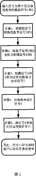
[0025] The method of the present invention requires a receiver, and the distance between the receiver and the receiver of the mobile phone using the method is such that the energy of the voice obtained by the receiver of the mobile phone is greater than the energy of the voice obtained by the receiver, and the two receivers obtain The noise energy of is of the same order of magnitude; the overall flow of the method of the present invention is shown in Figure 1. The method includes the following steps:
[0026] 1) Receiving the analog signals 1 and 2 output by the two receivers respectively, and converting the analog signals into digital signals 3 and 4;
[0027] 2) Transform the two output digital signals 3 and 4 into frequency domain signals 5 and 6;
[0028] 3) Detect the voice activation status according to the frequency domain signal and output signal 7;
[0029] 4) The output signal 7 according to the voice activation status suppresses noise to obtain a noise suppressed frequency domain signal 9;
[0030] 5) After transforming the frequency domain signal 9 into a time domain signal 11, a useful voice signal is output.
[0031] The two receivers of the present invention can be implemented in a variety of ways, for example:
[0032] The first implementation is shown in FIG. 2, the first receiver is the original receiver 43 of the mobile phone 41, and 42 is the original normal speaker. The second receiver is a newly installed receiver 44 (the specific installation method is conventional technology), which can be located on the back of the speaker 42 of the mobile phone at a distance 43 and can also receive noise well.
[0033] The second implementation is shown in Figure 3. The first receiver is the original receiver 53 of the mobile phone 51, and 52 is the original normal speaker. The second receiver is the receiver 55 of the wired or wireless headset 56 of the mobile phone. The mobile phone user can transmit the voice to the communicating party through the receiver 55 on 56. In order to achieve the effect of two receivers far and near, the user needs to place the receiver 55 close to the user's mouth, and place the receiver 53 far away from the receiver 55 to simulate the reception of the first method. The output of the receiver 55 is sent to an input terminal of step 2) through the digital voice signal obtained after the analog-to-digital conversion; the output of the receiver 53 does not need to pass through the analog-to-digital converter inherent in the wired or wireless earphone after passing through the analog-to-digital converter of the present invention. The digital voice signal is directly sent to the other input terminal of the step 2) of the present invention through digital conversion. The transmission method of the digital voice signal does not belong to the scope of the present invention, but belongs to a conventional method, such as using Bluetooth wireless transmission technology. Compared with the first implementation manner, this second implementation manner may not need to modify the mobile phone hardware.
[0034] The two receivers of the present invention are not limited to the above two implementation modes, and any two receivers obtained by other methods according to the principle of the present invention also belong to the scope of the present invention.
[0035] The working principle of using the method of the present invention to suppress the voice noise of the mobile phone is explained as follows:
[0036] The module for suppressing voice noise made by the method of the present invention is installed in a suitable place in the phone case, and the two input ends of the module are respectively connected to the above two receivers, and the output ends are connected to the input ends of the telephone. (Ie the port where the original telephone receiver is connected) can work.
[0037] In Figure 2 or Figure 3, use a and b to represent the distance between the two receivers and the speaker’s mouth, Ea and Eb to represent the energy of the useful voice signal received by the two receivers, and e and f to represent the noise The distance between the source and the two receivers, Ee and Ef are used to represent the energy of the noise received by the two receivers. Then the sound energy propagation attenuation is inversely proportional to the square of the distance. Under the reasonable assumptions b>>a (“>>” means much greater than) and f~e (“~” means approximately equal to), there is Ea /Eb>>1 and Ee/Ef~1. Signal 1 corresponds to the analog signal output by the receiver 43 in FIG. 2 or the receiver 55 in FIG. 3; signal 2 corresponds to the analog signal output by the receiver 44 in FIG. 2 or the receiver 53 in FIG. 3. The energy of signal 1 corresponds to Ea and Ee, and the energy of signal 2 corresponds to Eb and Ef. It can be known that signal 1 is composed of useful signals and noise signals, and signal 2 is composed of useful signals and noise signals of very small intensity. When the speaker speaks, signal 1 has a greater intensity than signal 2. When the speaker is not speaking, there is no useful signal, then signal 1 and signal 2 have basically the same strength.
[0038] Signals 3 and 4 are digital signals obtained by analog-to-digital conversion of signals 1 and 2, respectively, and frequency-domain signals are obtained after frequency-domain conversion of the digital signals. Voice activation detection judges whether the speaker is speaking by calculating the spectrum intensity of 5 and 6, that is, voice activation detection. Signal 7 is used to indicate this voice activation. When voice is activated, noise is suppressed by spectral amplitude subtraction and removal of residual noise components. When voice is not activated, noise suppressed signal is obtained by spectral amplitude subtraction and removing more residual noise components. Then, the frequency domain signal 9 output after noise suppression is transformed into the time domain and superimposed as a useful signal 11 to be transmitted to the call partner.
[0039] The embodiments of each step of the present invention are respectively described as follows:
[0040] In step 1) of the method of the present invention, a conventional analog-to-digital converter can be used to convert the analog signals output by the two receivers into digital signals.
[0041] In step 2) of the method of the present invention, the specific implementation method of transforming the two output digital signals into frequency domain signals is shown in Fig. 4, which performs serial-to-parallel conversion, windowing and Fourier transformation on the two input signals. The relationship between the output signal and the input signal and the specific calculation methods of serial-to-parallel conversion, windowing and Fourier transform are described in detail as follows:
[0042]In this embodiment, in order to facilitate processing, the two signals in the analog-to-digital conversion have the same sampling frequency. If they are different, the incoming signals 3 and 4 can have the same sampling frequency through up-sampling or down-sampling. It is also common to assume that signals 3 and 4 have the same sampling frequency. Let fs represent the sampling frequency. The frequency domain transform method is to process the input digital signals 3 and 4 in a frame manner. Use s3(n) and s4(n) to represent the values of signals 3 and 4 at the nth (non-negative integer) sampling point, respectively. Set the frame width as W, and when selecting parameters, W should be an even number, and the frame offset width should be P, which is also an even number. Use matrix vectors f3(m) and f4(m) to represent the data vectors of the mth (non-negative integer) frame corresponding to s3 and s4, respectively. Then there is the following relationship:
[0043] f3(m)=[s3(m*P)s3(m*P+1)...s3(m*P+W-1)]
[0044] f4(m)=[s4(m*P)s4(m*P+1)...s4(m*P+W-1)]
[0045] Use f5(m) and f6(m) to represent the output frequency domain signals 5 and 6 after processing the m-th frame, then
[0046] f5(m)=CHOP(FFT(H(f3(m))))
[0047] f6(m)=CHOP(FFT(H(f4(m))))
[0048] Among them, H represents the conventional window function, and FFT represents the Fourier transform. CHOP(x) represents a vector formed by taking the first half W/2+1 elements of vector x. Since the number of vector elements of f3(m) is W, the number of vector elements obtained after Fourier transform is also W, so the number of vector elements of f5(m) and f6(m) are both W/2+1. In the parameter selection, the window function H can be a symmetric Hamming window. If the embodiment selects the width of W so that the length of the speech signal processed in each frame is about 25 milliseconds, and selects P so that the frame offset ratio is about 40% of W, then
[0049] W=efix(0.025*fs)
[0050] P=efix(0.4*W)
[0051] Where efix(x) represents the even number closest to x. Using the above-mentioned embodiment method, when fs is 22.050 kHz, the above-mentioned parameter selection can achieve a good noise suppression effect.
[0052] The specific implementation of the voice activation detection method of the present invention is shown in FIG. 5, which includes calculating the amplitude of two input signals, calculating the amplitude decibels, calculating the mean value of the difference between the two amplitude decibels and the larger value of zero, and the voice activation threshold. Compare. The specific method is described in detail as follows:
[0053] The voice activation detection method judges whether the speaker is speaking in the mth frame by comparing the frequency spectrum of the two input signals. Use s7(m) to represent the voice activation detection value of the m-th frame output after voice activation detection. A detection value of 1 indicates that the voice is activated, that is, the speaker is talking; a detection value of 0 indicates that the voice is not activated, that is, the speaker does not Talking. Use T to represent the voice activation threshold (in decibels (dB)), then
[0054] If mean(max(pdb(abs(f5(m)))-pdb(abs(f6(m))), 0))>T, then s7(m)=1; otherwise s7(m)=0
[0055] The function abs(x) represents the magnitude of each element of the complex number x; the function pdb(x)=20*log10(x); log10 refers to the base 10 logarithm of each element of the vector; the function max(x, y ) Means taking the larger value of the corresponding elements of the vectors x and y; mean(x) means taking the average value of the elements of the vector x. When the present invention is applied, when T=5dB is selected, a good voice activation detection effect can be obtained.
[0056] The embodiment of the noise suppression method of the present invention is shown in FIG. 6. The noise suppression is to suppress noise by subtracting the spectral amplitude and removing the residual noise component when the voice is activated; when the voice is not activated, the noise is suppressed by the spectral amplitude. The method of subtracting and removing more residual noise components than when the voice is activated suppresses noise.
[0057] Its working principle is: signal 7 is a voice activation indication signal output by voice activation detection, and this information is used with signals 5 and 6 to suppress noise. The method of suppressing noise is to suppress noise by subtracting the spectral amplitude and removing residual noise components. Depending on whether the voice is activated or not, the degree of residual component removal is different. First, the calculation method of the residual noise component is explained. Use y5(m) and y6(m) to represent the amplitude values of the output frequency domain signals 5 and 6 after processing the m-th frame, respectively. Then there is the following relationship
[0058] y5(m)=abs(f5(m))
[0059] y6(m)=abs(f6(m))
[0060] The matrix vector i(q) is used to represent the residual noise component of the qth frame in all frames of non-voice activation (ie, s7(m) is equal to 0), and the number of vector elements of i(q) is equal to W. The average value of the residual noise component value is obtained by the method of statistical averaging, and is represented by the matrix component r, and the variance of the residual noise component is represented by v. Let L represent the number of statistical frames of residual noise components. Then the solving method of r and v can be described by the following natural language program. When this method is started, initialize u=0, r=zero vector, v=zero vector, and then perform the following operations for every m-th frame.
[0061] If s7(m) is equal to 0, then {
[0062] If u is equal to L, then {
[0063] r=((L-1)*r+max(y5(m)-y6(m), 0))/L
[0064] }
[0065] otherwise{
[0066] i(u)=max(y5(m)-y6(m), 0)
[0067] u=u+1
[0068] If u is equal to L, then {
[0069] r=(i(0)+i(1)+…+i(L-1))/L
[0070] v=((i(0)-r) 2 +(i(1)-r) 2 +...+(i(L-1)-r) 2 )/L
[0071] }
[0072] }
[0073] }
[0074] With the mean value and variance of the residual noise component, the output after noise suppression can be obtained. Let y9(m) represent the amplitude of the signal 9 after noise suppression in the m-th frame. Have
[0075] z=y5(m)-y6(m)-r
[0076] If s7(m) is equal to 1, then {
[0077] y9(m)=max(z-0.2*SQRT(v), 0)
[0078] }
[0079] otherwise{
[0080] zz=z-0.2*SQRT(v)
[0081] zzz=max(zz, 0)
[0082] Index d{ for each element of vector zz
[0083] If the absolute value of zz(d) is greater than the dth element of SQRT(v), then {
[0084] The dth element of y9(m)=0
[0085] }
[0086] otherwise{
[0087] The dth element of y9(m) = the dth element of zzz
[0088] }
[0089] }
[0090] }
[0091] Among them, SQRT(x) represents a vector consisting of the square root of each element of x. It can be seen from the above that when s7(m) is equal to 1, that is, the voice is activated, the amplitude of the noise suppressed signal y9(m) is obtained by subtracting y6(m) and the residual noise component from y5(m) ; In the case that s7(m) is equal to 0, that is, the voice is not activated, compare the signal zz(d) from which the mean value of the noise residual component has been subtracted from the square root of the variance of the noise residual component to obtain the amplitude y9 of the signal with more noise suppression (m). In this way, the output s9(m) after noise suppression can be obtained by the following calculation
[0092] Index d( for each element of vector y9(m)
[0093] The dth element of s9(m) = the dth element of y9(m)*e j*f5(m)的第d个元素的相位
[0094] }
[0095] Where j represents the imaginary unit, e j*x Represents cos(x)+j*sin(x). Experiments show that the noise suppression parameter L is selected as 9 to achieve a good noise suppression effect.
[0096] The embodiment of the time domain transform method of the present invention is shown in FIG. 7, and its function is to restore the frequency domain signal of the voice whose noise has been suppressed to the time domain. The restoration process consists of two steps: time domain restoration and time domain superposition. The specific method is as follows. The time-domain recovered signal t9(m) of the output s9(m) after noise suppression can be expressed as
[0097] t9(m)=REAL(IFFT(a9(m)))
[0098] Among them, IFFT stands for inverse Fourier transform, and REAL stands for taking the real part of a complex vector.
[0099] The method of obtaining a9(m) can be described in natural language as
[0100] d ranges from 0 to W-1{
[0101] If d is less than or equal to W/2, then {
[0102] the dth element of a9(m) = the dth element of s9(m)
[0103] }
[0104] otherwise{
[0105] The dth element of a9(m) = the conjugate of the W-dth element of s9(m)
[0106] }
[0107] }
[0108] It can be known that the number of elements in a9(m) is W, so the number of elements in t9(m) is also W, and t9(m) includes the time from the 0th to W-1th sampling points of the mth frame Domain value. For the convenience of description, use t9(m,n) to represent the value of the nth sampling point of t9(m). When n is less than 0 or n is greater than or equal to W, the defined sampling value is equal to 0. Then the time domain superimposed signal of t9(m), the output signal 11 after the time domain transformation can be expressed as:
[0109] s11(n)=t9(0,n)+t9(1,n-P)+t9(2,n-2P)+t9(3,n-3P)+...
[0110] Where n is a non-negative integer.