Rotating type shaver with a plurality of knife tackles

A rotary, shaver technology, applied in the field of multi-cutter rotary shavers, can solve the problems of user discomfort, difficult processing, poor performance, etc., and achieves improved shaving performance and shaving comfort, The effect of low manufacturing cost and increased contact area

Inactive Publication Date: 2007-09-26
SUPERMAN GROUP
View PDF0 Cites 10 Cited by
  • Summary
  • Abstract
  • Description
  • Claims
  • Application Information

AI Technical Summary

Problems solved by technology

[0010] The technical problem to be solved and the technical task proposed by the present invention are to overcome the defects of difficult processing, user's discomfort and poor performance exposed in the actual manufacture and use of the existing technical solutions, and to provide a convenient processing and good comfort. , multi-knife group rotary shaver with better comprehensive performance

Method used


Image

  • Rotating type shaver with a plurality of knife tackles
  • Rotating type shaver with a plurality of knife tackles
  • Rotating type shaver with a plurality of knife tackles

Examples


Embodiment 1

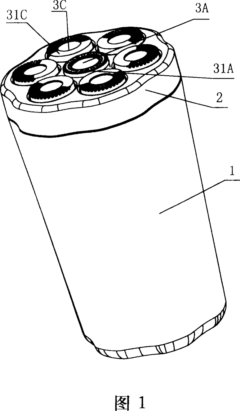
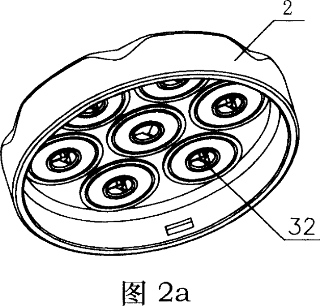
[0037] As shown in Figures 1, 2a, and 3b, the seven-blade rotary shaver has a housing 1 with a bracket 2 on which seven razor units are installed, wherein: the central razor unit 3A It consists of the outer cutter 31A and the inner cutter 32 , and the peripheral razor group 3C consists of the outer cutter 31C and the inner cutter 32 . Obviously, the inner cutters 32 used by the seven razor groups are the same (see Figure 2a), but there are two types of outer cutters: one is the outer cutter 31A of the central razor group, with a small circular hole The short must enter the beard hole, and the other is the outer cutter 31C with the long must enter the beard hole of the slit form on the protruding ring slightly more than half. In this seven-blade rotary shaver, one central razor unit 3A and six peripheral razor units 3C are mounted on the bracket 2 . Wherein, the razor group 3A is arranged on the central part of the bracket 2, and the remaining 6 peripheral razor groups 3C are ...

Embodiment 2

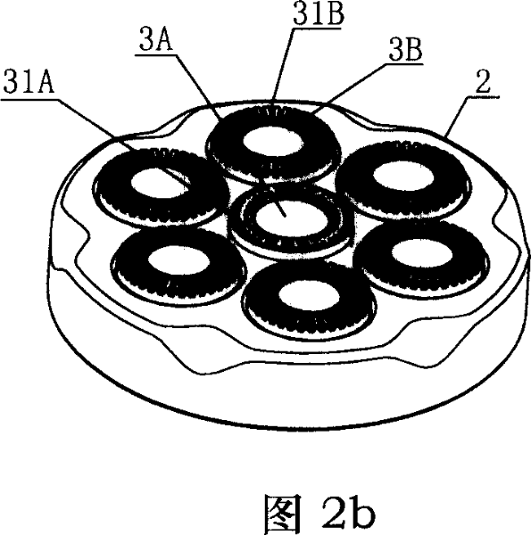
[0039] As shown in Figures 2b and 3a, the outer cutters 31B of the six peripheral razor groups 3B of the seven-blade rotary shaver have slit-type long beard inlet holes, thus forming the outer periphery of the shaver head. Part preliminary shaving area (long beard cutting and shaving area), which is the difference from Embodiment 1; all the other structures are the same as Embodiment 1, and will not be repeated here.

Embodiment 3

[0041] As shown in Figure 4a, in the four-blade rotary shaver, one razor unit 3A and three razor units 3B are installed on the bracket 2, wherein one central razor unit 3A is arranged in the center of the bracket 2 On the position, the remaining three peripheral razor sets 3B are evenly arranged around the razor set 3A. The outer cutting knife 31A of the central razor group 3A has a small circular hole-shaped short beard inlet hole, thereby forming a root-aligned shaving area (short beard cutting area) at the center of the shaver head, and the remaining three peripheral razors The outer cutter 31B of the group 3B has a slit-shaped long beard inlet hole, thereby forming a preliminary shaving area (long beard cutting area) on the periphery of the shaver head.


PUM


Abstract

The invention relates to a rotary shaver with multiple tool groups, comprising a shell with bracket. At least four razor groups are set on the bracket. Each razor group comprises an external cutter contacting with skin in shaving and an internal cutter which can be driven to rotate relatively to the external cutter. It is characterized in that a razor group in said razor groups is set in the centering position to be centering razor group and residual razor groups are set round the centering razor group to be peripheral razor groups; beard inlet holes for only short beard are set on the convex circle ring of external cutter of said centering razor group to form centering short-beard cutting region; beard inlet holes for only long beard are set on convex circle rings of external cutters of said peripheral razor groups to form peripheral long-beard cutting region. The invention is provided with good skin feeling in shaving, more comfortable feeling in shaving. It is favor of improving the shaving speed and make shaving quicker. It is also provided with small difficulty and low producing cost.

Description

technical field [0001] The present invention relates to a rotary shaver, in particular to a multi-blade rotary shaver with two different types of beard-feeding areas provided on the outer cutter. Background technique [0002] Prior art multi-blade rotary shavers have a housing with a cradle on which are mounted a plurality of razor units, each of which is controlled by an outer cutter that contacts the skin during shaving It consists of an inner cutter that can be driven to rotate relative to the outer cutter. The outer cutter is arranged on the bracket according to the distribution mode to be mentioned below, and has the beard inlet hole of the type to be mentioned below: [0003] 1. A plurality of outer cutting knives are arranged on a concentric circle on the bracket, such as Pinzi, Tianzi, and hexagonal, instead of being arranged according to the central part and the peripheral parts around it. The center portion is not provided with an outer cu...

Claims


Application Information

Patent Timeline
Patent Type & Authority Applications(China)
IPC IPC(8): B26B19/14
Inventor 应平祥
Owner SUPERMAN GROUP
Why Eureka
Try Eureka