Check patentability & draft patents in minutes with Patsnap Eureka AI!

Linear compressor assembly

A shaft, driving coil technology, applied in the field of compressors

Inactive Publication Date: 2007-09-26
INGERSOLL RAND CO
View PDF0 Cites 7 Cited by
  • Summary
  • Abstract
  • Description
  • Claims
  • Application Information

AI Technical Summary

Problems solved by technology

In medium and larger size electric linear compressors, heat buildup causes such a problem that it becomes a limiting factor in compressor design

Method used


Image

  • Linear compressor assembly
  • Linear compressor assembly
  • Linear compressor assembly

Examples


Embodiment Construction

[0013] Before explaining any embodiment of the invention in detail, it is to be understood that the invention is not limited in its application to the details of construction and arrangement of parts set forth in the following description or illustrated in the drawings. The invention is capable of other embodiments and of being practiced or carried out in various ways. Also, it is to be understood that the phraseology and terminology used herein are for the purpose of description and should not be regarded as limiting.

[0014] In this disclosure, the terms compressor or pump will be used interchangeably as a mechanism designed to displace a working fluid from one location to another.

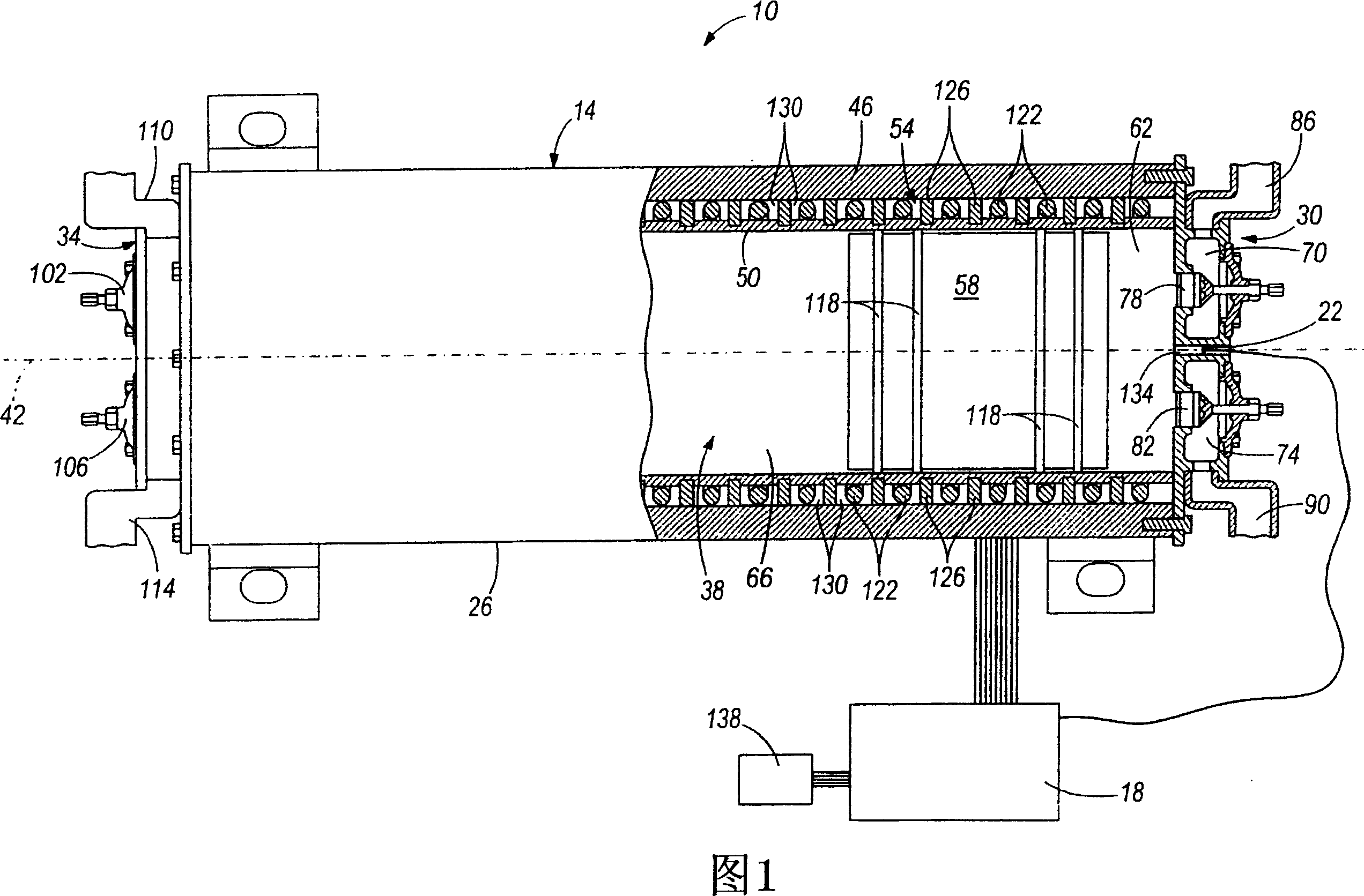
[0015] FIG. 1 schematically shows an electrically linearly actuated compressor 10 . Compressor 10 includes housing 14 , controller 18 and sensor 22 . The housing 14 includes a cylindrical central portion 26 and two end portions 30 and 34 at opposite ends of the central portion 26 . The centr...


PUM


Abstract

A linear compressor assembly includes a housing having a bore formed therein, the bore being axially oriented along a first axis, a piston reciprocally disposed within the bore, and a plurality of drive coils adjacent the bore for energizing the drive coils to produce a magnetic field capable of displacing the piston within the bore substantially along the first axis. A controller is used for selectively controlling energizing of the drive coils. A cooling system is at least partially disposed in the housing and the cooling system is used for cooling the apparatus.

Description

[0001] Cross References to Related Applications [0002] This application claims priority to US Patent Application No. 11 / 388,432, filed March 24, 2006, entitled "Linear Compressor Assembly," by Robert K. Haseley. technical field [0003] The present application relates to a compressor, and more particularly to an electrically driven linear actuated compressor. Background technique [0004] Linear actuator systems are used to displace variable elements such as railroad tracks and precision displacement machinery in closed loop and extension systems. The position of elements propelled by linear actuators has been shown to be determined by changes in current and voltage through the respective drive coils. For example, a low pressure in one of the drive coils will indicate the passage of a piston adjacent to that drive coil. Controlling an electrically linearly actuated pump or compressor is a very complex design challenge. Therefore, it is important to have a sensor that is...

Claims


Application Information

Patent Timeline
Patent Type & Authority Applications(China)
IPC IPC(8): F04B35/04F04B39/06F04B49/06H02K9/19
CPCH02K5/20F04B35/045H02K41/03F04B17/04F04B39/064H02K55/02Y02E40/622Y02E40/60H02K5/203
Inventor 罗伯特·K·哈斯里
Owner INGERSOLL RAND CO
Features
  • R&D
  • Intellectual Property
  • Life Sciences
  • Materials
  • Tech Scout
  • Unparalleled Data Quality
  • Higher Quality Content
  • 60% Fewer Hallucinations
Learn More