Setups modus of short-circuit-proof spiral baffle plate shell-and-tube heat exchanger draw rod
A technology of shell-and-tube heat exchangers and spiral baffles, which is applied in the direction of heat exchanger types, heat exchanger shells, indirect heat exchangers, etc., and can solve the problems affecting the heat exchange efficiency of equipment and the number of tie rods
Inactive Publication Date: 2007-09-26
宋小平 +1
View PDF0 Cites 3 Cited by
- Summary
- Abstract
- Description
- Claims
- Application Information
AI Technical Summary
Problems solved by technology
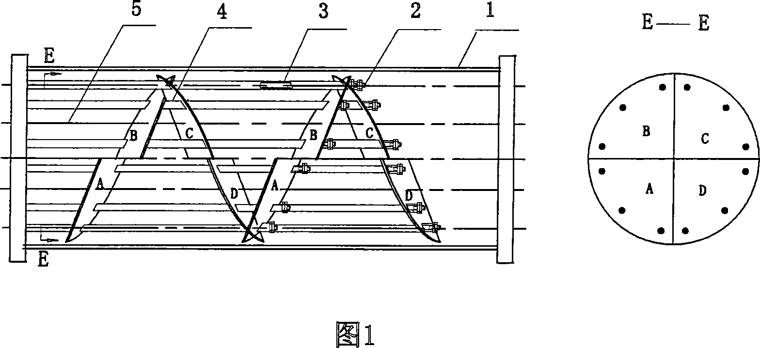
At the same time, since the adjacent baffles have no overlapping parts, the tie rods (2) on the baffles cannot be shared, resulting in a large number of tie rods, and because the tie rods occupy the position of the heat exchange tube (5), the heat exchange efficiency of the equipment is affected
Method used
View moreImage
Smart ImageViewing Examples

Examples
Embodiment Construction
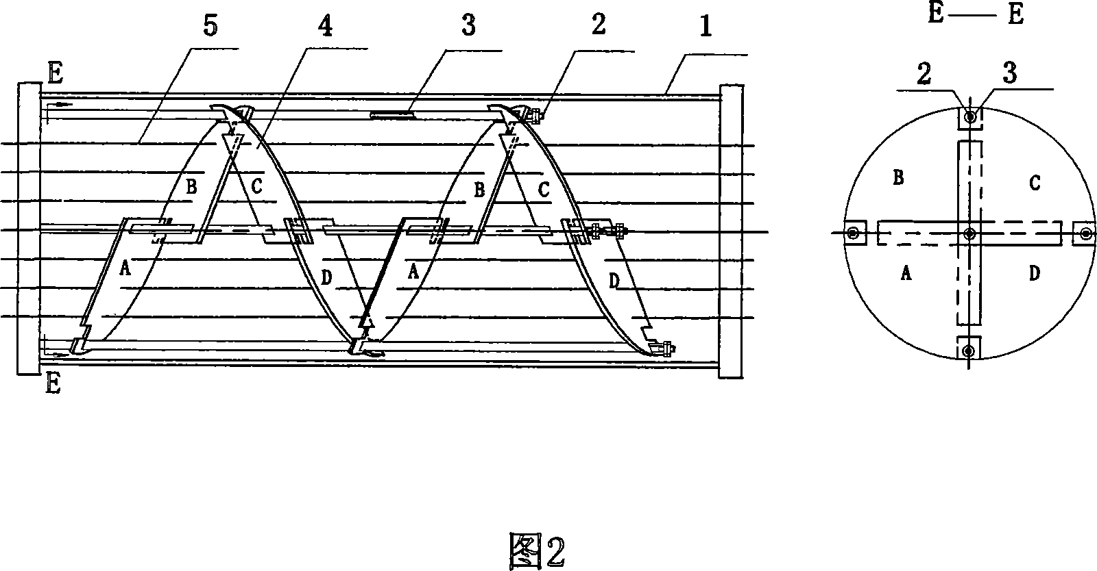
[0006] A pitch of the helical propulsion of the shell channel is composed of four fan-shaped baffles with the same number of quadrants, and the straight side of each baffle is increased by 10mm to 100mm in width, and the widening width depends on the diameter of the equipment and the angle of the baffles. When assembling, the widened part of the straight side of the baffle is overlapped, and the tie rod is used to pass through the overlapping part of the baffle on the axis of the shell and the vertical line passing through the center of the shell, and the distance tube is set on the pull rod to fix the adjacent quadrant folds A baffle and a baffle behind the same quadrant.
Login to View More PUM
 Abstract
It aims to solve the low heat exchange issue of common tubular shell spiral folding plate, and it features in each projection being 360degree / 4 fan baffle plate with two straight lines extended to 10mm to 100 mm, with the pulling pole going through the central axial line of the shell and two vertical line through the overlapping part of the baffle plate, using pipe spacer to position the baffle plate.
Description
(1) Technical field [0001] The invention relates to a shell-and-tube type spiral baffle heat exchanger in the technological process of petroleum, chemical industry, power generation, metallurgy, food, pharmaceutical and other industries. (2) Background technology [0002] Ordinary shell-and-tube spiral baffle heat exchanger is a kind of high-efficiency and energy-saving partition wall heat exchange equipment. The baffle mode of the medium in the shell is spiral baffle, as shown in Figure 1, a pitch of the shell channel helically propelled is composed of four fan-shaped baffles (4) A, B, C, and D with the same number of quadrants. Each fan-shaped baffle and the axis of the housing (1) form a certain angle, and are arranged in sequence from the front of the housing to the rear of the housing. A triangular space is formed between the fan-shaped baffles of two adjacent quadrants, which is easy to make along the The medium flowing through the fan-shaped baffle forms a short-circ...
Claims
Login to View More Application Information
Patent Timeline
 Patent Type & Authority Applications(China)
IPC IPC(8): F28F9/007F28F9/24
CPCF28F27/02F28D7/16F28F9/22F28F2009/228Y02P20/10
Inventor 宋小平裴志中
Owner 宋小平