Focusing structural

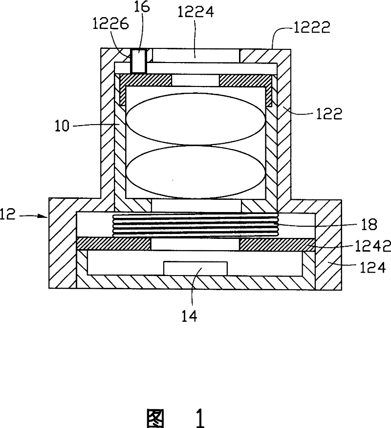
一种传动机构、成像模组的技术,应用在对焦结构领域,能够解决影响对焦结构寿命、不方便对焦、易阻挡采光孔1224入射光线等问题,达到寿命长、操作简单的效果

Inactive Publication Date: 2007-09-26
SHENZHEN FUTAIHONG PRECISION IND CO LTD
View PDF1 Cites 2 Cited by
  • Summary
  • Abstract
  • Description
  • Claims
  • Application Information

AI Technical Summary

Problems solved by technology

[0004] The focusing structure realizes the function of focusing through the cooperation of the screw 16 and the spring 18, but the spring 18 has a certain life span, thereby affecting the life span of the focusing structure; in addition, the screw 16 abuts against one side of the lens 10, so that both sides of the lens The force is uneven and tilted; the screw 16 is close to the lighting hole 1224, and it is easy to block the incident light of the lighting hole 1224 during manual operation, which makes it inconvenient to focus

Method used


Image

  • Focusing structural
  • Focusing structural
  • Focusing structural

Examples


Embodiment Construction

[0014] The focusing structure of the preferred embodiment of the present invention is applied to a portable electronic device. This embodiment takes a digital camera as an example for illustration.

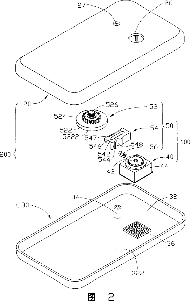
[0015] Referring to FIG. 2 , the focusing structure 100 of the preferred embodiment of the present invention is applied to a digital camera 200 , and the focusing structure 100 includes an imaging module 40 and a transmission mechanism 50 .

[0016] Please refer to FIG. 3 , the digital camera 200 includes a first casing 20 and a second casing 30 .

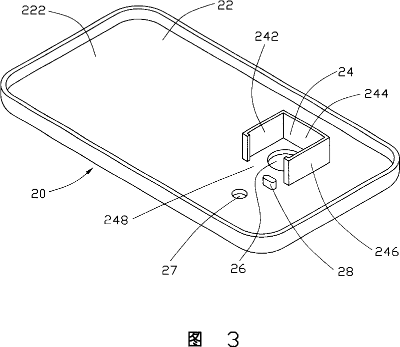
[0017] The first housing 20 is in the shape of a cover and has an upper cavity 22 . The upper cavity 22 has a bottom surface 222 , and one side of the bottom surface 222 is provided with an accommodating portion 24 for fixing the imaging module 40 and preventing it from moving. The accommodating portion 24 is surrounded by a bottom surface 222 and three side walls 242, 244, 246 extending from the bottom surface 222, wherein the two en...


PUM


Abstract

This invention provides one focus calibration structure, which comprises imaging module set and drive structure, wherein, the imaging set comprises lens cylinder and socket matched by rotation; the drive structure comprises drive parts, passive parts and drive bar; the drive part matches with passive part; the drive bar is connected to passive part and lens cylinder to drive the cylinder move to socket.

Description

【Technical field】 [0001] The present invention relates to a focusing structure. 【Background technique】 [0002] With the development of multimedia technology, digital cameras and video cameras are more and more favored by consumers. While people are pursuing miniaturization of digital cameras and video cameras, they also put forward higher requirements for the imaging quality of the objects they shoot. The focus structure is a key component to ensure the clear effect of the recorded image, and it is used to adjust the distance between the lens and the image sensor so that the image plane falls on the imaging surface of the image sensor. [0003] Chinese Patent No. 200320125240 published on March 30, 2005 discloses a focusing structure. Please refer to FIG. 1 , the focusing structure includes a lens 10 , a lens holder 12 , an image sensor 14 , a screw 16 and a spring 18 . The lens mount 12 includes a first cylindrical portion 122 and a second cylindrical portion 124, wherei...

Claims


Application Information

Patent Timeline
Patent Type & Authority Applications(China)
IPC IPC(8): G02B7/04
CPCG02B7/08G02B13/001
Inventor 葛鹏进郭耿辉刘晔王军涂小华陈家骅
Owner SHENZHEN FUTAIHONG PRECISION IND CO LTD
Why Eureka
Try Eureka