
Transformer and iron core set thereof

A technology of transformers and iron cores, used in transformers, transformer/inductor cores, variable transformers, etc.

Inactive Publication Date: 2007-09-26
DELTA ELECTRONICS INC
View PDF0 Cites 3 Cited by
  • Summary
  • Abstract
  • Description
  • Claims
  • Application Information

AI Technical Summary

Problems solved by technology

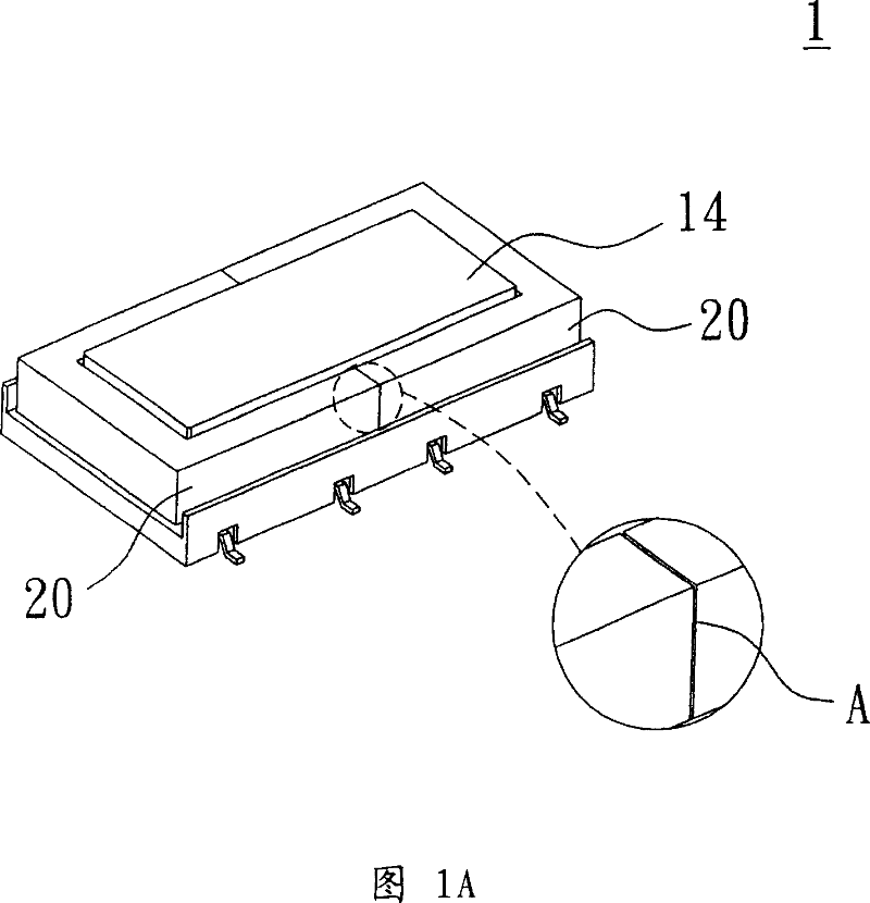
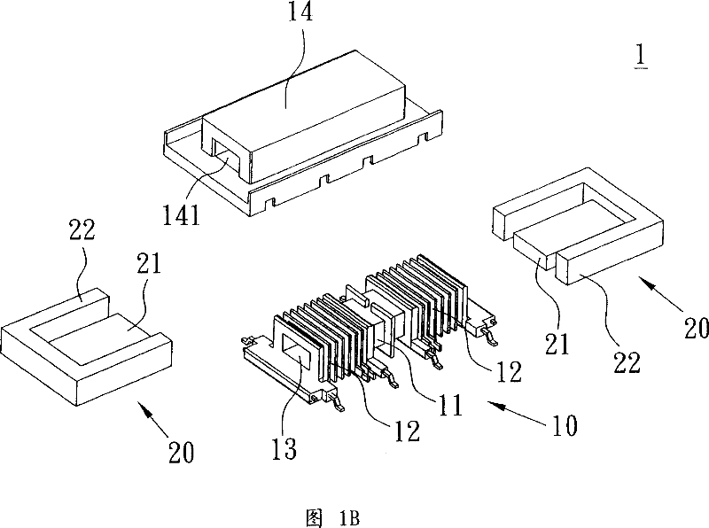
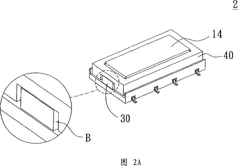
[0007] The air gap B (as shown in FIG. 2A ) of the above-mentioned second type transformer 2 is generated between the first iron core 30 and the two protrusions 41 of the second iron core 40, and the adjustment of the leakage inductance can only rely on Adjust the size of the air gap, adjust the distance or the number of turns between the primary coil and the secondary coil, but this will also cause many deficiencies in the aforementioned first type of transformer, and it cannot meet the needs of current manufacturers or consumers. Expected by the users, so it is necessary to eliminate or improve

Method used


Image

  • Transformer and iron core set thereof
  • Transformer and iron core set thereof
  • Transformer and iron core set thereof

Examples


Embodiment Construction

[0045] Please refer to Fig. 3A and shown in Fig. 3B, it is the first preferred embodiment of the transformer of the present invention, wherein the transformer 3 is made up of a bobbin 10 and an iron core group, wherein the iron core group also includes a first An iron core 30 and a second iron core 50 . The winding frame 10 has a primary winding area 11 and two secondary winding areas 12, the primary winding area 11 is located in the middle section of the winding frame 10, and the two secondary winding areas 12 are located in the On both sides of the primary winding area 11, the primary winding area 11 can be wound by one or two sets of primary coils (not shown in the figure), and the secondary winding areas 12 can respectively provide a set of secondary coils ( not shown in the figure), in addition, the winding frame 10 is axially provided with a perforation 13; the first iron core 30 is I-shaped and penetrates the perforation 13 of the winding frame 10; the second iron core ...


PUM


Abstract

The invention provides a transformer that mainly comprises a bobbin, the first iron core and the second iron core, the bobbin possesses a primary coiling area and a secondary coiling area, the first iron core is set through the bobbin, the second iron core is mounted on the bobbin, and the second iron core possesses the first protruding part which bestraddles the bobbin, and the second protruding part which is formed integrally on the second iron core and between the first protruding part, and the second protruding part is between the primary coiling area and a secondary coiling area.

Description

technical field [0001] The invention relates to a transformer and its iron core group, in particular to a transformer and its iron core group capable of improving leakage inductance. Background technique [0002] As displays are increasingly required to reduce thickness, liquid crystal displays (LCDs) are gradually replacing traditional cathode ray tubes (CRTs) through the advantages of small thickness, stable image quality and no flickering; and in LCD screens, It has a backlight module, and the backlight module also includes a cold cathode lamp driven by high voltage, which is used as the light source of the backlight system for displaying. This kind of lamp is generally driven by an inverter. In addition to having In addition to the driving circuit, it also includes a high-voltage transformer to form. [0003] Although the thickness of liquid crystal displays is much smaller than that of conventional cathode ray tubes, consumers demand that the size of the screen be bigg...

Claims


Application Information

Patent Timeline
Patent Type & Authority Applications(China)
IPC IPC(8): H01F29/00H01F27/24H01F27/04
Inventor 曾祥益吴成丰
Owner DELTA ELECTRONICS INC
Learn More