System for biasing T-shaped head and controlling antenna

A bias and control signal technology, applied in the field of communication, can solve the problems of heavy workload, limited versatility, low applicability, etc., and achieve the effect of reducing installation workload, reducing cost, and avoiding poor applicability

Active Publication Date: 2007-09-26
HUAWEI TECH CO LTD
View PDF0 Cites 35 Cited by
  • Summary
  • Abstract
  • Description
  • Claims
  • Application Information

AI Technical Summary

Problems solved by technology

[0018] The embodiments of the present invention provide the following technical solutions to solve the technical problems of high cost when upgrading the electronically adjustable antenna, or low applicability, limited versatility, and relatively large installation and construction workload after upgrading to the electronically adjustable antenna of:

Method used


Image

  • System for biasing T-shaped head and controlling antenna
  • System for biasing T-shaped head and controlling antenna
  • System for biasing T-shaped head and controlling antenna

Examples


Embodiment 1

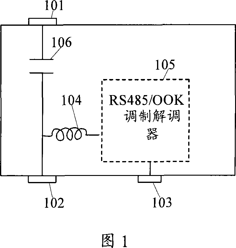
[0057] Embodiment 1, in the embodiment of the present invention, the offset T-shaped head structure can also be shown in Figure 6. The implementation of DSBT (DCPASS-SBT) is that the antenna port of the standard SBT is connected to a direct current. The principle comparison between the standard SBT and the DSBT is as follows As shown in Figure 1 and Figure 6, it can be seen that the DC input of port 2 is introduced into port 1 through the inductor in the DSBT, then port 1 can receive DC and provide DC for the tower top amplifier.

[0058] Referring to Figure 6, the structure diagram of Embodiment 1 of the present invention includes:

[0059] Port1601 is used to transmit radio frequency signals through the DC blocking capacitor 604 and Port2602; transmit the DC through the second inductor 607 and Port2602; this port is also connected to the tower-mounted amplifier to transmit DC to the tower-mounted amplifier;

[0060] The DC blocking capacitor 604 is used to connect Port1601 a...

Embodiment 2

[0066] Embodiment 2, in the embodiment of the present invention, the offset T-shaped head structure can also be as shown in Figure 8, the implementation of DSBT (DC PASS-SBT) is that the antenna port of the standard SBT is connected to a direct current, and the principle of the standard SBT and DSBT As shown in Figure 1 and Figure 7, it can be seen that the DC output part of port 3 (that is, the DC output from the power wire of the AISG interface) is connected to port 1 through a wire in the DSBT, then port 1 can receive DC. Provide the required DC for the tower mounted amplifier.

[0067] Referring to Figure 7, the structure diagram of Embodiment 2 of the present invention includes:

[0068] Port1701 is used to transmit radio frequency signals through the DC blocking capacitor 704 and Port2702; it is connected to Port3703 to receive the direct current transmitted by Port3703;

[0069] The DC blocking capacitor 704 is used to connect Port1701 and Port2702 to transmit the radi...

Embodiment 3

[0074] Embodiment 3, in the embodiment of the present invention, the offset T-shaped head structure is shown in Figure 8, the implementation of DSBT (DC PASS-SBT) is that the antenna port of the standard SBT is connected to direct current, and the principle comparison between the standard SBT and DSBT is shown in the figure 1. As shown in Figure 8, it can be seen that the DC blocking capacitor in the standard SBT circuit is removed in Embodiment 3, and DC is allowed to be sent to the antenna port. In this way, part of the DC coming from the feeder flows to the AISG interface, and the power supply regulation For the antenna, a part penetrates the antenna port to the TMA to provide it with DC.

[0075] Referring to Figure 8, the structure diagram of Embodiment 3 of the present invention includes:

[0076] Port1801, used to receive DC from the second port, and transmit RF signals with Port2802; this port is connected to the tower mounted amplifier, and transmits DC to the tower m...


PUM


Abstract

The invention discloses a offset T type head that comprises the first port, the second port, the third port, blocking condenser, the first inductance, the second inductance, modem, thereinto, the second inductance is used to connect the first port, the second port transmits said direct current; the invention also provides a system which controls antenna that comprises electricity controlled antenna drive motor unit, electricity controlled antenna, tower top amplifier, offset T type head and base station; according to the offset T type head of the invention, when the non- electricity controlled antenna is updated to the electricity controlled antenna, there is no need to be instead of STMA, so the cost is decreased, the electricity controlled antenna controller is not added, and the technique problem of poor applicability using electricity controlled antenna controller can be avoided, and the base station do not need to provide connection port, without longer cable, the amount of work is decreased.

Description

technical field [0001] The invention relates to the communication field, in particular to a system for biasing a T-shaped head and controlling an antenna. Background technique [0002] SBT (Smart Bias Tee, intelligent bias T-shaped head) is a device that can cooperate with the electric adjustable antenna and RCU (Remote Control Unit, electric adjustable antenna drive motor unit) to realize the electronic adjustable antenna function. Please refer to Figure 1, the following describes the structure of the standard SBT in detail, see Figure 1, the standard SBT includes: [0003] Port1101, which is connected to Port2102 through a DC blocking capacitor 106 for radio frequency signal transmission; [0004] Inductance 104, one end is connected with DC blocking capacitor and Port2102; the other end is connected with RS475 / OOK modem 105; [0005] Port2102 is connected with DC blocking capacitor 106 and inductor 104, and this port transmits control signals and DC; [0006] The RS475...

Claims


Application Information

Patent Timeline
Patent Type & Authority Applications(China)
IPC IPC(8): H04B7/02H01Q3/26
CPCH01Q3/26
Inventor 马国田周建军姚娜
Owner HUAWEI TECH CO LTD
Why Eureka
Try Eureka