Motion controller and system identifying method

A motion control device and system identification technology, applied in control systems, general control systems, control/regulation systems, etc., can solve problems such as inability to calculate inertia, inability to remove viscous friction or Coulomb friction fixed interference, etc.

Inactive Publication Date: 2007-09-26
YASKAWA DENKI KK
View PDF1 Cites 6 Cited by
  • Summary
  • Abstract
  • Description
  • Claims
  • Application Information

AI Technical Summary

Problems solved by technology

[0011] Due to the two constraints listed above, the existing inertia estimation device has the problem that, for example, the influence of fixed disturbances such as viscous friction, Coulomb friction, and gravity cannot be removed during one positioning operation, and the inertia cannot be estimated.

Method used


Image

  • Motion controller and system identifying method
  • Motion controller and system identifying method
  • Motion controller and system identifying method

Examples


Embodiment 1

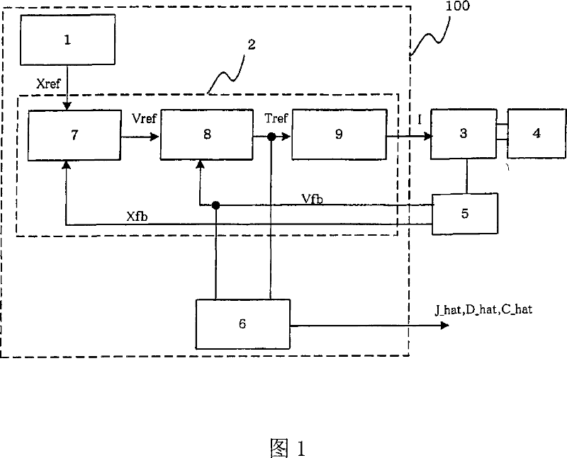
[0100] FIG. 1 is a block diagram showing the structure of a motion control device implementing the method of the present invention. In the figure, 1 is a command generator that issues a position command Xref. 2 denotes a controller, which performs a control operation and outputs a current I according to a position command, a position detection value Xfb, and a speed detection value Vfb. The operation inside the controller 2 can be in any form. In this specific embodiment, it is the position controller 7 that outputs the speed command Vref according to the position command Xref and the position detection value Xfb, and outputs the speed command Vref and the speed detection value Vfb The speed controller 8 for the torque command value Tref and the current controller 9 for controlling to output current according to the torque command value are constituted. Here, the speed detection value may be a value obtained by time-differentiating the position detection value, and in the cas...

Embodiment 2

[0162] The second method of the present invention will be described below.

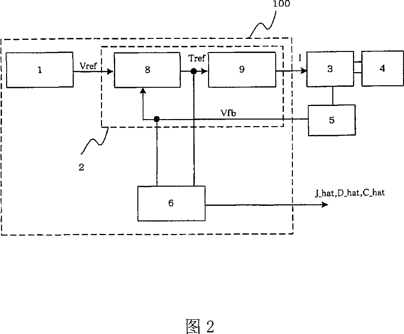
[0163] FIG. 1 is a block diagram showing the configuration of a motion control device implementing the method of the present invention. Since this figure was described in Embodiment 1, its description is omitted.

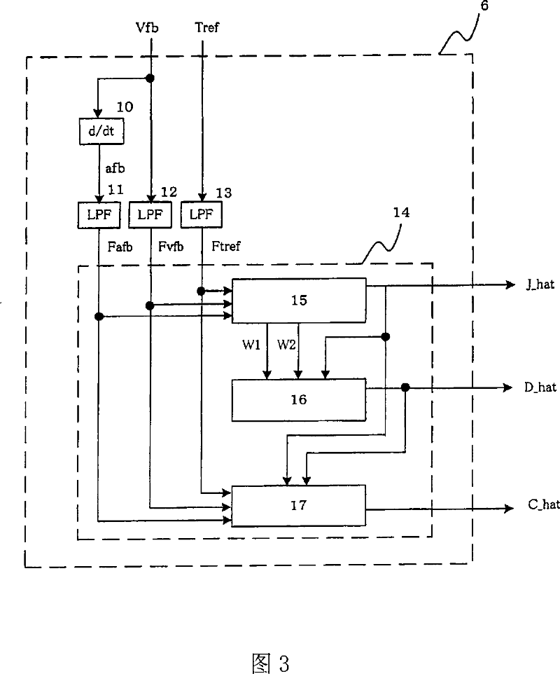
[0164] Fig. 7 is a block diagram showing the internal processing of the recognizer 6, and since it is different from Fig. 3, it will be described below. In the figure, 10 denotes a time differentiator that time-differentiates the speed detection value Vfb to calculate the acceleration detection value afb. Here, in the case of digital control, the time differential calculation may use an approximate differential obtained by dividing the signal difference between this time and the previous time by the control period. 11, 12, and 13 denote a first filter, a second filter, and a third filter, respectively. The filter used here may be a filter whose order of the denominator is three or more hi...


PUM


Abstract

A motion controller accurately identifies system constants, such as inertia, viscous friction coefficient, and constant disturbance, without requiring operation, even in cases where viscous friction and / or constant disturbance are present. An identifier includes a time-differentiator for calculating an acceleration detection value afb by time-differentiating a speed detection value Vfb, a first filter for calculating Fafb by filtering the acceleration detection value afb, a second filter for calculating Fvfb by filtering the speed detection value Vfb, a third filter for calculating Ftref by filtering a torque command value Tref, and a JDC estimator for calculating an inertia identification value J_hat, a viscous friction coefficient identification value D_hat, and a constant disturbance identification value C_hat of a control object by performing time-differentiation and four arithmetic operations based on Ftref, Fvfb and Fafb.

Description

technical field [0001] The present invention relates to a motion control device and a system identification method capable of accurately calculating the inertia, viscous friction coefficient, and fixed disturbance of a control object. Background technique [0002] The device for calculating the inertia of the existing motor adopts the following method: the torque command value and the torque command value of the model are integrated within a certain period of time, and their ratio is multiplied by the nominal value of inertia for calculation. At this time, a specific Actions to remove fixed disturbances such as viscous friction, Coulomb friction, and gravity to improve accuracy (for example, refer to Patent Document 1). [0003] In FIG. 9 , 3 is a motor, and 4 is a machine coupled to the motor. A detector 5 is attached to the motor 3. 71 is a command generating unit which outputs a motor operating speed command vref. 72 is a speed control part which performs proportional-i...

Claims


Application Information

Patent Timeline
Patent Type & Authority Applications(China)
IPC IPC(8): H02P29/00G05B13/02H02P23/14
Inventor 萩原淳
Owner YASKAWA DENKI KK
Why Eureka
Try Eureka